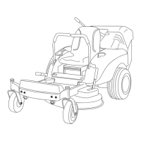
Operation in the Recycler
®
Mode
Air is required to cut and recut g rass clippings in
the mo w er housing, so do not set the height-of-cut
too lo w or completely sur round the housing b y
uncut g rass . Alw a ys tr y to ha v e one side of the
mo w er dec k free from uncut g rass; allo wing air
to be dra wn into the mo w er dec k. W hen making
an initial cut through the center of an uncut area,
operate the mac hine slo w er and bac k up if the
mo w er star ts to clog .
T o ensure optim um perfor mance , clean the
underside of the mo w er housing after eac h use .
If residue is allo w ed to build up in the mo w er
housing, cutting perfor mance can decrease .
F or the best perfor mance of the R ecycler
®
mode:
• Mo w regularly .
• K ee p air flo w high b y o v erlapping cutting paths
• Use an higher height of cut for taller g rass .
• Use shar p blades .
• T ra v el at slo w er speeds when mo wing taller
g rass .
Positioning the Seat
T he seat can mo v e forw ard and bac kw ard.
P osition the seat where y ou ha v e the best control
of the mac hine and are most comfor table .
1. Raise the seat and loosen the adjustment knobs
enough to mo v e the seat ( Figure 20 ).
Important: Mak e sur e that the spacer s
stay in place when loosening the knobs
to mo v e the seat. Loss of the spacer s can
r esult in dama ge to the seat.
2. Mo v e the seat to the desired position and
tighten the knobs .
Figure 20
1. Adjustment knobs
Adjusting the Motion
Control Levers
T he motion control lev ers can be adjusted higher
or lo w er for maxim um operator comfor t.
1. R emo v e the 2 bolts holding the control lev er
to the control ar m shaft ( Figure 21 ).
2. Mo v e the control lev er to the next set of holes .
Secure the lev er with the 2 bolts ( Figure 21 ).
Figure 21
1. Control lever 3. Control arm shaft
2. Bolt
3. R e peat the adjustment for the opposite control
lev er .
24

 Loading...