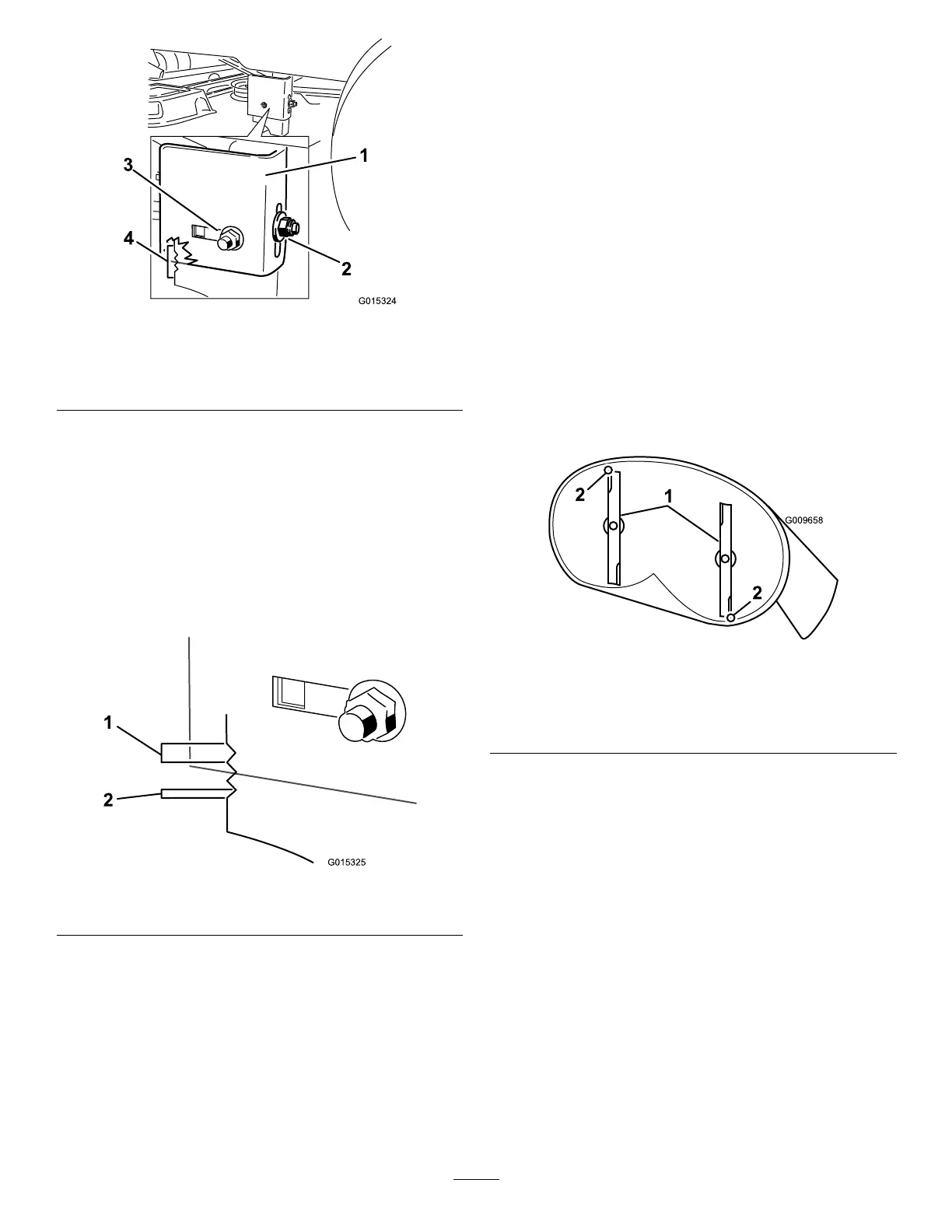
Figure50
1.Hangerbracket
3.Sidelockingnut,slotted
position.
2.Rearlockingnut4.Adjustmentnotches
10.Loosenthesidelockingnutonthehangerbracketjust
enoughtoallowthehangertobeadjusted(Figure50).
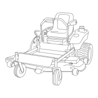
11.Usethenotchesontheweldedbrackettomeasurethe
amountofadjustment.
Note:Eachnotchsurfaceisequivalentto6.35mm
(1/4inch),whileasinglesideis3.2mm(1/8inch)as
showninFigure51.
12.Adjusttheheightofthemowerdecktothedesired
height.
Figure51
1.6.35mm(1/4inch)2.3.2mm(1/8inch)
13.Stopthedeckattheadjustedposition,andtightenthe
sidelockingnutonthehangerbrackettoholdthenew
position(Figure50).
14.Tightentherearlockingnutonthehangerbracket.
15.Continuelevelingthedeckbycheckingthefront-to-rear
bladeslope;referto
AdjustingtheFront-to-RearBlade
Slope(page35).
AdjustingtheFront-to-RearBlade
Slope
Checkthefront-to-rearbladelevelanytimeyouinstallthe
mower.Ifthefrontofthemowerismorethan7.9mm
(5/16inch)lowerthantherearofthemower,adjusttheblade
levelusingthefollowinginstructions:
1.Parkthemachineonalevelsurfaceanddisengagethe
blade-controlswitch.
2.Movethemotion-controlleversoutwardtothepark
position,stoptheengine,removethekey,andwaitfor
allmovingpartstostopbeforeleavingtheoperating
position.
3.Settheheight-of-cutlevertomiddleposition.
Note:Checkandadjusttheside-to-sidebladelevelif
youhavenotcheckedthesetting;referto
Side-to-Side
Leveling(page34).
4.Carefullyrotatethebladessotheyarefacingfrontto
rear(Figure52).
Figure52
MowerDeckswith2Blades
1.Bladesfronttorear
2.Measurefromthetipofthebladetotheatsurfacehere
5.Measurefromthetipofthefrontbladetotheat
surface,andthetipoftherearbladetotheatsurface
(
Figure52).
Note:Ifthefrontbladetipisnot1.6to7.9mm(1/16
to5/16inch)lowerthantherearbladetip,adjustthe
frontlocknut.
6.Toadjustthefront-to-rearbladeslope,rotatethe
adjustmentnutinthefrontofthemower(Figure53).
35