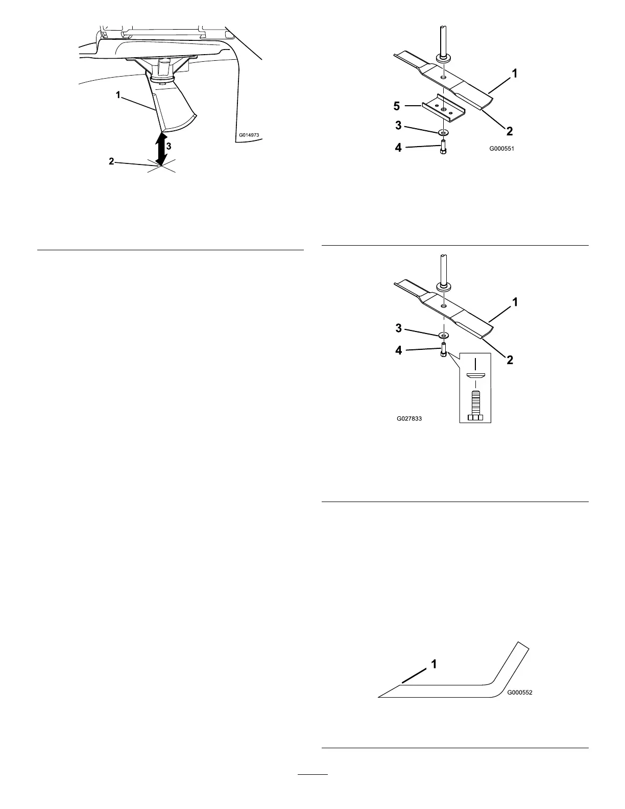
g014973
Figure60
1.Oppositebladeedge(inpositionformeasuring)
2.Levelsurface
3.Secondmeasureddistancebetweenbladeandsurface(B)
A.IfthedifferencebetweenAandBisgreater
than3mm(1/8inch),replacethebladewith
anewblade;refertoRemovingtheBlades
(page43)andSharpeningtheBlades(page
43).
Note:Ifabentbladeisreplacedwitha
newblade,andthedimensionobtained
continuestoexceed3mm(1/8inch),the
bladespindlecouldbebent.Contactan
AuthorizedServiceDealerforservice.
B.Ifthevarianceiswithinconstraints,moveto
thenextblade.
6.Repeatthisprocedureoneachblade.
RemovingtheBlades
Thebladesmustbereplacedifasolidobjectishit,if
thebladeisoutofbalance,orifthebladeisbent.For
bestperformanceandcontinuedsafetyconformance
ofthemachine,usegenuineT ororeplacementblades.
Replacementbladesmadebyothermanufacturers
mayresultinnon-conformancewithsafetystandards.
1.Holdthebladeendusingaragorthickly-padded
glove.
2.Removethebladestiffener(32-inchdecksonly),
bladebolt,thecurvedwasher,andtheblade
fromthespindleshaft(Figure61andFigure62).
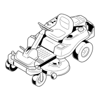
g000551
Figure61
81cm(32-Inch)Decks
1.Sailareaoftheblade
4.Bladebolt
2.Blade
5.Bladestiffener
3.Curvedwasher
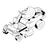
g027833
Figure62
107cm(42-Inch)Decks
1.Sailareaoftheblade3.Curvedwasher
2.Blade4.Bladebolt
SharpeningtheBlades
1.Usealetosharpenthecuttingedgeatboth
endsoftheblade(Figure63).
Note:Maintaintheoriginalangle.
Note:Thebladeretainsitsbalanceifthesame
amountofmaterialisremovedfrombothcutting
edges.
g000552
Figure63
1.Sharpenatoriginalangle.
43