g004536
Figure114
LeftandCenterSpindleShown
1.Sailareaoftheblade3.Curvedwasher
2.Blade4.Bladebolt
g024248
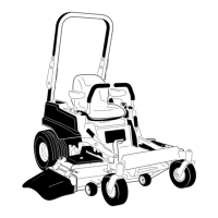
Figure115
Bladelocation
1.Frontofmowerdeck4.Counter-rotatingblade
2.Right-threadedbladebolts
5.Left-threadedbladebolt
3.Regularblades
SharpeningtheBlades
1.Usealetosharpenthecuttingedgeatboth
endsoftheblade(Figure116).
Note:Maintaintheoriginalangle.
Note:Thebladeretainsitsbalanceifthesame
amountofmaterialisremovedfrombothcutting
edges.
g000552
Figure116
1.Sharpenatoriginalangle.
2.Checkthebalanceofthebladebyputtingiton
abladebalancer(Figure117).
Note:Ifthebladestaysinahorizontalposition,
thebladeisbalancedandcanbeused.
Note:Ifthebladeisnotbalanced,lesome
metalofftheendofthesailareaonly(Figure
116).
g000553
Figure117
1.Blade2.Balancer
3.Repeatthisprocedureuntilthebladeis
balanced.
InstallingtheBlades
Side-DischargeMachines
1.Installthebladeontothespindleshaft(Figure
113).
Important:Thecurvedpartoftheblade
mustpointupwardtowardtheinsideofthe
mowertoensurepropercutting.
2.Installthecurvedwasherandbladebolt(Figure
113).
Note:Installthecurved-washerconetoward
thebolthead.
3.T orquethebladeboltto115to150N∙m(85to
110ft-lb).
71
 Loading...