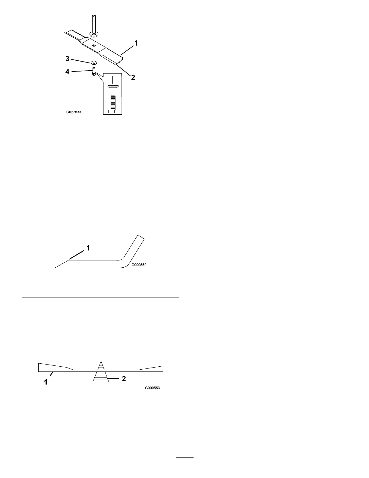
g027833
Figure59
1.Sailareaoftheblade3.Curvedwasher
2.Blade4.Bladebolt
SharpeningtheBlades
1.Usealetosharpenthecuttingedgeatboth
endsoftheblade(Figure60).
Note:Maintaintheoriginalangle.
Note:Thebladeretainsitsbalanceifthesame
amountofmaterialisremovedfrombothcutting
edges.
g000552
Figure60
1.Sharpenatoriginalangle.
2.Checkthebalanceofthebladebyputtingitona
bladebalancer(Figure61).
Note:Ifthebladestaysinahorizontalposition,
thebladeisbalancedandcanbeused.
Note:Ifthebladeisnotbalanced,lesome
metalofftheendofthesailareaonly(Figure60).
g000553
Figure61
1.Blade2.Balancer
3.Repeatthisprocedureuntilthebladeis
balanced.
InstallingtheBlades
1.Installthebladeontothespindleshaft(Figure
59).
Important:Thecurvedpartoftheblade
mustbepointingupwardtowardtheinside
ofthemowertoensurepropercutting.
2.Installthecurvedwasher(cuppedsidetoward
theblade)andthebladebolt(Figure59).
3.Torquethebladeboltto81to108N∙m(60to
80ft-lb).
LevelingtheMowerDeck
Checktoensurethatthemowerdeckislevelanytime
youinstallthemowerorwhenyouseeanunevencut
onyourlawn.
Checkthemowerdeckforbentbladespriorto
leveling,andremoveandreplaceanybentblades;
refertotheServicingtheCuttingBlades(page42)
beforecontinuing.
Levelthemowerdeckside-to-siderst;thenyoucan
adjustthefront-to-rearslope.
Requirements:
•Themachinemustbeonalevelsurface.
•Alltiresmustbeproperlyinated;refertoChecking
theTirePressure(page39).
CheckingtheSide-to-SideLevel
1.Parkthemachineonalevelsurface,disengage
theblade-controlswitch(PTO),andmovethe
motion-controlleversoutwardtothePARK
position.
2.Shutofftheengine,removethekey,andwait
forallmovingpartstostopbeforeleavingthe
operatingposition.
3.Settheheightofcutto76mm(3inches).
4.Carefullyrotatethebladessidetoside.
5.Measurebetweentheoutsidecuttingedgesand
theatsurface(Figure62andFigure63).
Note:Ifbothmeasurementsarenotwithin5
mm(3/16inch),anadjustmentisrequired;refer
toLevelingfromSidetoSide(page46).
44