AdjustingtheMotion
ControlNeutral-LockPivot
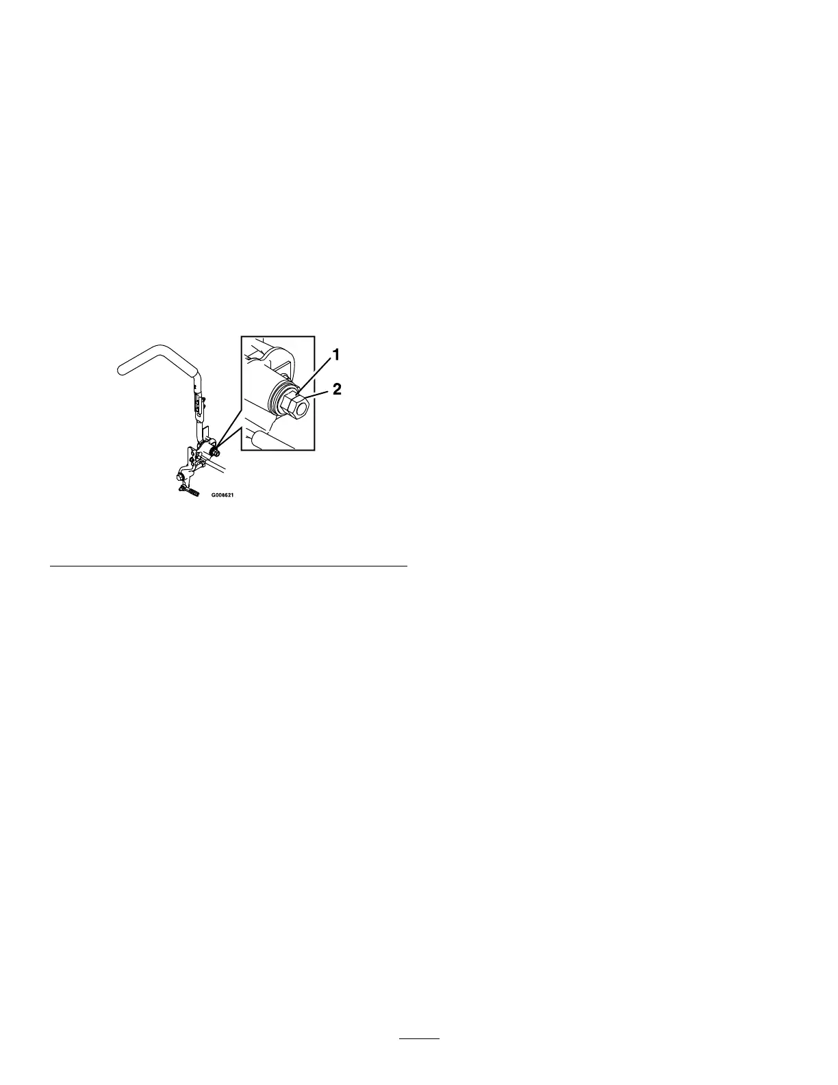
Youcanadjusttheangednuttoobtainamore
desiredmotion-controlleverresistancewhenmoving
ittotheNEUTRAL-LOCKposition(Figure86).
1.Loosenthejamnut.
2.Tightenorloosentheangednuttothedesired
feel.
Note:Formoreresistance,tightentheanged
nut.
Note:Forlessresistance,loosentheanged
nut
3.Tightenthejamnut.
g008621
Figure86
1.Flangednut2.Jamnut
HydraulicSystem
Maintenance
HydraulicSystemSafety
•Ensurethatallhydraulic-uidhosesand
linesareingoodconditionandallhydraulic
connectionsandttingsaretightbefore
applyingpressuretothehydraulicsystem.
•Keepyourbodyandhandsawayfrompinhole
leaksornozzlesthatejecthigh-pressure
hydraulicuid.
•Usecardboardorpapertondhydraulicleaks.
•Safelyrelieveallpressureinthehydraulic
systembeforeperforminganyworkonthe
hydraulicsystem.
•Seekimmediatemedicalattentionifuid
isinjectedintoskin.Injecteduidmustbe
surgicallyremovedwithinafewhoursbya
doctor.
ServicingtheHydraulic
System
Hydraulic-FluidType:Toro
®
HYPR-OIL
™
500
hydraulicuidorMobil
®
115W-50.
Important:Usethespecieduid.Otheruids
coulddamagethehydraulicsystem.
EachHydraulicSystemFluidCapacity:1.5L(52
oz)persidewithlterchange
CheckingtheHydraulicFluid
ServiceInterval:Every50hours—Checkthe
hydraulic-uidlevel.
1.Positionthemachineonalevelsurface.
2.Disengagetheblade-controlswitch(PTO),move
themotion-controlleverstotheNEUTRAL-LOCK
position,andengagetheparkingbrake.
3.Shutofftheengine,removethekey,andwait
forallmovingpartstostopbeforeleavingthe
operatingposition.
4.Allowtheengineandthehydraulicsystemto
coolfor10minutes.
Note:Theoillevelonthedipstickisincorrect
whentheoilischeckedandtheunitishot.
5.Movetheseatforward.
6.Cleantheareaaroundthedipsticksof
hydraulic-systemreservoirs(Figure87).
7.Remove1dipstickfromthehydraulicreservoir
(Figure87).
61