Installation
11
1
m–3518
2
3
4
5
6
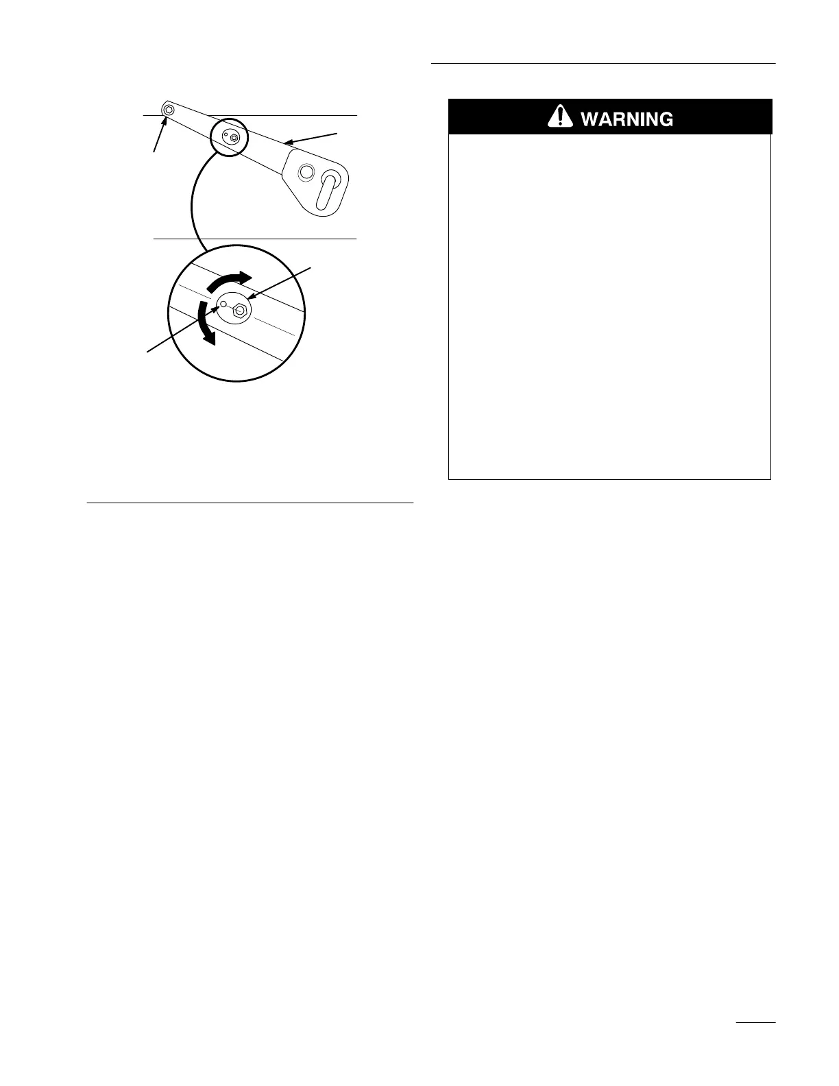
Figure 18
Right Side of T
ractor Shown
1. Indicator
2. Adjustment
cam
3.
Lift arm
4.
Pivot point
5.
Lowers front of deck
6.
Raises front of deck
2. If they are not, park the machine on a level
surface, set the parking brake, lower the
attachment lift to take pressure off the cams, and
turn the ignition key to “STOP” to stop the
engine. Remove the ignition key.
POTENTIAL HAZARD
• The “scissor” formed by the mower
mounting brackets and the attachment lift
arm is dangerous.
WHAT CAN HAPPEN
• Hands and fingers can get caught between
the mower parts and the tractor and be
injured.
HOW TO AV
OID THE HAZARD
• Keep hands away from moving parts while
operating the attachment lift.
• Set the parking brake, lower the
attachment lift, turn the ignition key to
“STOP” to stop the engine, and remove the
ignition key before making any
adjustments.
3. Loosen the nuts on the cams, rotate the cams to
the proper position, then tighten the cam nuts.
4. Start the tractor, raise the attachment lift and turn
the ignition key to “STOP” to stop the engine.
Remove the ignition key.
5. Check the slope of one of the blades (Fig. 15).
A. Measure the distance from the front tip of
the blade to the flat surface.
B. Carefully rotate the blade tip until it is in
the rear position.
C. When the blade tip is in the front position,
it should be approximately 1/4” (7 mm)
lower than when it is in the rear position.
6. If it is not, start the tractor, lower the attachment
lift to take pressure off the cams, and turn the
ignition key to “STOP” to stop the engine.
Remove the ignition key.