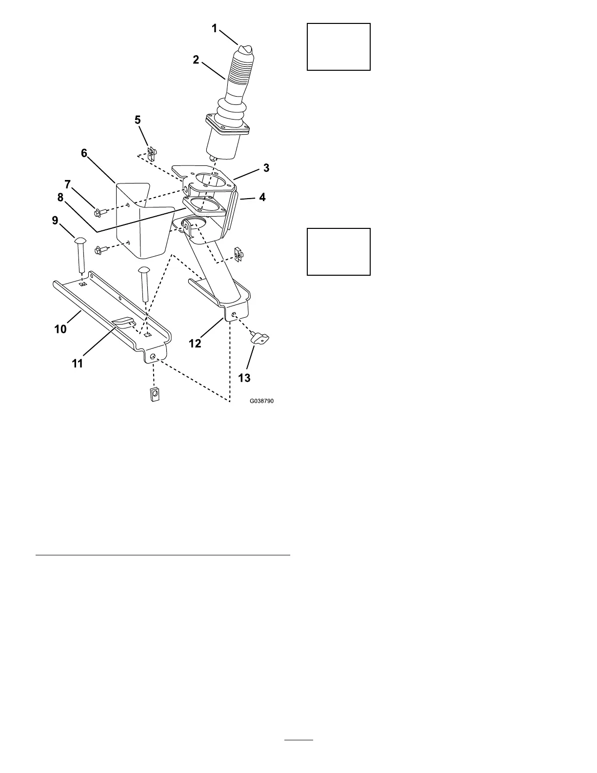
Figure4
1.Toggleswitch8.Joystick-mountingplate
2.Joystick
9.Carriagebolts
3.Joystickpod10.Joystickpodmounting
bracket
4.Decalhere(applyonthe
sideofthejoystickpod)
11.Tab
5.Clip(2)
12.Joystickpodbase
6.Joystickpodcover13.Knob
7.Hex-headscrews(1/4x
5/8inch)
2.Slidethebottombracketofthejoystickassemblyalong
thebracketuntilitstopsunderthetabonthejoystick
podmountingbracket.
3.Insertthethumbscrewthroughtheholeinthefrontof
thebottombracketofthejoystickandtightenitrmly
byhand.
4.Connectthewireendonthejoysticktotheappropriate
connectoronthewireharness.
5.Applythedecaltothejoystickpod(Figure4).
5
ConnectingtheBattery
NoPartsRequired
Procedure
Connectthenegative(–)batterycabletothebattery.
Note:Whenthekitisproperlyinstalled,thepowerpoint
andfuseblockshouldhavepoweronlywhentheignition
switchisintheONposition.
6
DownloadingtheSoftware
NoPartsRequired
Procedure
Important:ThisstepmustbeperformedbyaToro
CommercialProductsDistributorServicestaffperson.
Note:YouwillneedalaptopPC(withthecurrentversion
ofToroDiagsoftwareloadedontoit)andacommunication
cableforUSBtoCANforToroDiag.
Note:Verifythatthesoftwarerevisionisatthecurrent
releaselevel.
1.DownloadthecurrentversionofToroDiagsoftware
availablefromtheToroDistributorPortalwebsite.
Note:Ifthemachinehasnotyetbeenconvertedto
theToroDiag,locatetheloop-backconnectoronthe
mainmachinewireharness(locatednearthemain
machinecontroller),andremoveit.Replacethisplug
withthecapwithouttheloopwireasindicatedinthe
ToroDiagservicebulletin.
2.PlugtheCANcommunicationcableintotheCAN
communicationsportlocatednearthemaincontroller
onthemainwireharness.
3.Followtheinstructionsonthescreenforprogramming
and/orre-programmingthesoftwareontheaccessory
controllerandthemainmachine.
5

 Loading...


