EasyManua.ls Logo

Toro Groundsmaster 3280-D Service Manual

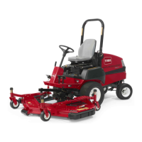
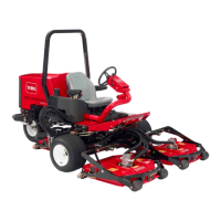
Toro Groundsmaster 3280-D
508 pages
To Next Page IconTo Next Page
Page #1 background imageLoading...
Page #1 background image
FormNo.05138SLRevB
Groundsmaster
®
3280-D/3320
(Models30307,30308,30309,30343,30344,
and30345)
©2018—TheToro®Company
8111LyndaleAvenueSouth
Bloomington,MN55420
OriginalInstructions(EN)
Contactusatwww.Toro.com.
AllRightsReserved

Table of Contents

Other manuals for Toro Groundsmaster 3280-D

Questions and Answers:

Toro Groundsmaster 3280-D Specifications

General IconGeneral
BrandToro
ModelGroundsmaster 3280-D
CategoryLawn Mower
LanguageEnglish

Summary

Preface

DANGER Safety Symbol

Safety symbol indicating danger and serious injury or death.

WARNING Safety Symbol

Safety symbol indicating warning and serious injury.

CAUTION Safety Symbol

Safety symbol indicating caution and minor to moderate injury.

IMPORTANT Notices

Notices providing important instructions to prevent damage.

Chapter 1 Safety

Safety Instructions

Instructions for safe operation, transport, maintenance, and storage.

Jacking Instructions

Procedures for safely lifting and supporting the machine.

Safety and Instructional Decals

Information on safety and instructional decals affixed to the machine.

Chapter 2 Specifications and Maintenance

Specifications

Details machine specifications and recommended service intervals.

Torque Specifications

Recommended fastener torque values for installation and tightening.

Shop Supplies

Common shop supplies recommended for use in procedures.

Special Tools

Special tools required for specific service procedures.

Chapter 3 Gasoline Engine

Specifications

Specifications for the Groundsmaster 3320-G gasoline engine.

General Information

General information about the gasoline engine used in the Groundsmaster 3320.

Adjustments

Procedures for adjusting engine controls and speed.

Service and Repairs

Information on servicing and repairing engine systems.

Chapter 4 Diesel Engine

Specifications

Specifications for the Groundsmaster 3280-D diesel engine.

General Information

General information about the diesel engine used in the Groundsmaster 3280-D.

Adjustments

Procedures for adjusting the throttle control.

Service and Repairs

Information on servicing and repairing diesel engine systems.

Chapter 5 Hydraulic System

Specifications

Specifications for the hydraulic system of Groundsmaster 3280-D and 3320.

General Information

General information on hydraulic system operation and maintenance.

Hydraulic Schematics

Diagrams illustrating the hydraulic system flow and components.

Hydraulic Flow Diagrams

Detailed explanations of hydraulic circuit operation in different modes.

Special Tools

Special tools required for hydraulic system testing and service.

Troubleshooting

Common problems and potential solutions for hydraulic system issues.

Testing the Hydraulic System

Procedures and precautions for testing hydraulic system performance.

Chapter 6 Electrical System

General Information

General information about the electrical system components.

Standard Control Module (SCM)

Information on the Standard Control Module that monitors and controls electrical components.

Standard Control Module Logic Chart

Chart detailing the logic for SCM inputs and outputs.

Special Tools

Special tools required for electrical system testing and service.

Troubleshooting

Common electrical problems and their possible causes.

Electrical System Quick Checks

Basic checks for battery and charging system functionality.

Checking the Operation of the Interlock Switches

Procedures for verifying the proper operation of safety interlock switches.

Adjustments

Procedures for adjusting the traction neutral sensor and parking brake switch.

Testing the Electrical Components

Procedures for testing various electrical components.

Fuses (Machine Serial Number below 400000000)

Identification and function of fuses for specific serial number range.

Fuses (Machine Serial Number above 400000000)

Identification and function of fuses for specific serial number range.

Operator Cab Fuses (Machines with Operator Cab)

Identification and function of fuses located in the operator cab.

Key Switch

Testing procedures for the machine's key switch.

Indicator Lights

Testing procedures for various indicator lights on the console.

Hour Meter

Procedure for testing the hour meter.

PTO Switch

Testing procedures for the PTO switch.

Deck Lift Switch (Machine Serial Numbers above 311000000)

Testing procedures for the deck lift switch.

Seat Switch

Testing procedures for the operator seat switch.

Windshield Washer/Wiper Switch (Machines with Operator Cab)

Testing procedures for the windshield washer/wiper switch.

Accessory Power Switch (Machines with Operator Cab)

Testing procedures for the accessory power switch.

Fan Speed Switch (Machines with Operator Cab)

Testing procedures for the fan speed switch.

Work Light Switch (Machines with Operator Cab–Optional)

Testing procedures for the optional work light switch.

Traction Neutral Switch (Machine Serial Numbers below 316000000)

Testing and adjusting the traction neutral sensor.

Traction Neutral Sensor (Machine Serial Number above 316000000)

Testing and adjusting the traction neutral sensor.

Parking Brake Switch

Testing and adjusting the parking brake switch.

High Temperature Warning Switch

Testing the high temperature warning switch.

High Temperature Shutdown Switch

Testing the high temperature shutdown switch.

Engine Oil Pressure Switch

Testing the engine oil pressure switch.

Relays (Groundsmaster 3280-D)

Information on the glow relay and accessory relay.

Lift Control Valve Solenoid Valve Coils (Machine Serial Number above 311000000)

Testing procedures for the lift control valve solenoid valve coils.

PTO Electric Clutch

Testing procedures for the PTO electric clutch.

Fuel Stop Solenoid (Groundsmaster 3280-D)

Testing procedures for the fuel stop solenoid.

Glow Controller (Groundsmaster 3280-D)

Information on the glow controller and its operation.

Fuel Pump (Groundsmaster 3280-D)

Information on testing the fuel pump capacity.

Fuel Pump (Groundsmaster 3320)

Information on testing the fuel pump capacity.

Fuel Pump Relay (Groundsmaster 3320)

Testing procedures for the fuel pump relay.

Battery Storage

Guidelines for storing the machine's battery.

Battery Care

Procedures for maintaining the battery and preventing corrosion.

Servicing the Battery

Procedures for servicing the battery, including specifications.

Charging the Battery

Procedures for charging the battery using a slow charging method.

Chapter 7 Chassis

Specifications

Specifications for chassis components like tire pressure and lug nut torque.

General Information

General information pertaining to the operator cab and servicing.

Service and Repairs

Procedures for servicing and repairing chassis components.

Wheels

Procedures for removing and installing wheels.

Steering Column

Procedures for removing and installing the steering column.

Rear Frame and Axle Assembly

Procedures for removing and installing the rear frame and axle assembly.

Rear Axle (2-Wheel Drive)

Procedures for removing the rear axle assembly.

Servicing the Rear Axle (2-Wheel Drive)

Procedures for servicing the rear axle pivot bushings and steering pivot bushings.

Rear Wheel Bearings (2-Wheel Drive)

Procedures for disassembling and assembling rear wheel bearings.

Operator Seat

Procedures for removing and installing the operator seat.

Mechanical Seat Suspension

Information on the mechanical seat suspension components.

Pneumatic Seat Suspension

Information on the pneumatic seat suspension components.

Lift Arms

Procedures for removing and installing the lift arms.

Chapter 8 Drive Axles

Specifications

Specifications for axle fluids, lubricants, and capacities.

General Information

General information on front and rear axles.

Front Axle

Description and diagrams of the front axle assembly.

4-Wheel Drive Rear Axle

Description and diagrams of the 4-wheel drive rear axle.

Special Tools

Special tool for differential gear holder.

Service and Repairs

Procedures for servicing and repairing drive axle components.

Servicing the Brake

Procedures for disassembling and assembling the brake system.

Front Axle Shafts and Bearings

Procedures for disassembling and assembling front axle shafts and bearings.

Front Axle (Machine Serial Number before 316000000)

Exploded view and parts list for the front axle.

Front Axle (Machine Serial Number after 316000000)

Exploded view and parts list for the front axle.

Servicing the Front Axle

Procedures for disassembling and assembling the front axle.

Ring to Pinion Gear Engagement (Front Axle)

Procedure for verifying and adjusting ring to pinion gear contact.

Rear Axle Driveshaft (4-Wheel Drive)

Procedures for removing and installing the rear axle driveshaft.

Servicing the Rear Axle Driveshaft Cross and Bearing (4-Wheel Drive)

Procedures for servicing the driveshaft cross and bearing.

Rear Axle (4-Wheel Drive)

Exploded view and procedures for the 4-wheel drive rear axle.

Bevel Gear Case and Axle Case (4-Wheel Drive Axle)

Procedures for removing and installing the bevel gear case and axle case.

Differential Shafts (4-Wheel Drive Axle)

Procedures for removing and installing differential shafts.

Axle Shafts (4-Wheel Drive Axle)

Procedures for removing and installing axle shafts.

Input Shaft/Pinion Gear (4-Wheel Drive Axle)

Procedures for removing and installing the input shaft/pinion gear.

Differential Gear Assembly (4-Wheel Drive Axle)

Procedures for removing, inspecting, and installing the differential gear assembly.

Pinion Gear to Ring Gear Engagement (4-Wheel Drive Axle)

Procedure for checking and adjusting pinion to ring gear contact.

Bi-Directional Clutch (4-Wheel Drive)

Procedures for removing and installing the bi-directional clutch.

Servicing the Bi-Directional Clutch (4-Wheel Drive)

Procedures for servicing the bi-directional clutch components.

Chapter 9 PTO System

General Information

General information about the PTO system.

Service and Repairs

Procedures for servicing and repairing PTO system components.

PTO Drive Belt

Information on the PTO drive belt.

PTO Driveshaft

Procedures for removing and installing the PTO driveshaft.

Servicing the PTO Driveshaft Cross and Bearing

Procedures for servicing the driveshaft cross and bearing.

PTO Shaft

Procedures for removing and installing the PTO shaft.

Aligning the PTO Pulley to the Electric Clutch Pulley

Procedure for aligning PTO and electric clutch pulleys.

Chapter 10 Cutting Units

General Information

General information about the cutting units.

Specifications

Specifications for various cutting units.

Cutting Unit Operator's Manual

Reference to the operator's manual for cutting unit information.

Troubleshooting

Factors affecting cutting quality and potential solutions.

Factors That Can Affect Quality of Cut

Lists factors influencing the quality of cut and their corrections.

Adjustments

Adjustment procedures for cutting units.

Castor Wheel Tire Pressure

Recommended tire pressure for castor wheels on the cutting deck.

Service and Repairs

Procedures for servicing and repairing cutting deck components.

Cutting Deck

Procedures for cutting deck removal and installation.

Idler Assembly

Procedures for removing and installing the idler assembly.

Blade Spindle

Procedures for removing and installing blade spindles.

Servicing the Blade Spindle

Procedures for disassembling and assembling the blade spindle.

Gearbox

Procedures for removing and installing the gearbox.

Castor Forks and Wheels

Procedures for disassembling and assembling castor forks and wheels.

Cutting Deck Rollers and Skids

Procedures for removing and installing cutting deck rollers and skids.

Chapter 11 Operator Cab

General Information

General information pertaining to the operator cab.

Operator’s Manual

Reference to the operator's manual for machine operation details.

Electrical Components and Schematics

Information on electrical components and schematics for the operator cab.

Cab Heater System

Components and operation of the cab heater system.

Service and Repairs

Procedures for servicing and repairing operator cab components.

Roof Assembly

Procedures for removing and installing the roof assembly.

Heating Components

Identification of heating components within the operator cab.

Mixing Box Assembly

Procedures for removing and installing the mixing box assembly.

Heater Core

Procedures for removing and installing the heater core.

Blower Fan

Procedures for removing and installing the blower fan.

Windshield Wiper Assembly

Procedures for disassembling and assembling the windshield wiper assembly.

Appendix A Foldout Drawings

Electrical Drawing Designations

Abbreviations and color codes used in electrical schematics and wire harness drawings.

Hydraulic Schematic-3280-D (Serial Numbers 311000001 through 316000000)

Hydraulic schematic for specific serial number ranges.

Hydraulic Schematic-3280-D (Machine Serial Numbers after 316000000)

Hydraulic schematic for specific serial number ranges.

Electrical Schematic-3320

Electrical schematic for the 3320 model.

Electrical Schematic (Machine Serial Number before 311000000)

Electrical schematic for specific serial number ranges.

Electrical Schematic (Machine Serial Number 311000000 and Up)

Electrical schematic for specific serial number ranges.

Electrical Schematic-Operator Cab

Electrical schematic specific to the operator cab.

Wire Harness Drawing-Main-3320 (Serial Numbers below 260000000)

Wire harness drawing for specific serial number ranges.

Wire Harness Drawing-Main-3280-D (Serial Numbers below 260000000)

Wire harness drawing for specific serial number ranges.

Wire Harness Drawing-Main-3280-D (Machine Serial Number 260000000 to 270000600)

Wire harness drawing for specific serial number ranges.

Wire Harness Drawing-Main-3280-D (Machine Serial Number 270000601 to 311000000)

Wire harness drawing for specific serial number ranges.

Wire Harness Drawing-Main-3280-D (Machine Serial Number 311000000 to 316000000)

Wire harness drawing for specific serial number ranges.

Wire Harness Drawing-Main-3280-D (Machine Serial Number 316000000 to 400000000)

Wire harness drawing for specific serial number ranges.

Wire Harness Drawing-Main-3280-D (Machine Serial Number 400000000 and Up)

Wire harness drawing for specific serial number ranges.

Wire Harness Drawing-Cab Model 30298 Power

Wire harness drawing for cab power supply.

Wire Harness Drawing-Cab Model 30298 Headliner

Wire harness drawing for the cab headliner.

Wire Harness Drawing-Cab Model 30298 Front Mount Accessory Power Supply

Wire harness drawing for front mount accessory power supply.

Wire Harness Drawing-Cab Model 30298 Heat/Air Conditioning Blower

Wire harness drawing for cab heat/air conditioning blower.

Wire Harness Drawing-Light Kit Model 30405 (Machines without Cab)

Wire harness drawing for light kit on machines without a cab.