HydraulicSystem
Maintenance
Thereservoirislledatthefactorywithapproximately
4.7liters(5quarts)ofhighqualitytractor
transmission/hydraulicuid.Therecommended
replacementuidisasfollows:
ToroPremiumTransmission/HydraulicTractorFluid
(Availablein5gallonpailsor55gallondrums.Seeparts
catalogorauthorizedT orodistributorforpartnumbers.)
Alternateuids:IftheT orouidisnotavailable,
Mobil®424hydraulicuidmaybeused.
Note:T orodoesnotassumeresponsibilityfor
damagecausedbyimpropersubstitutions.
Note:Manyhydraulicuidsarealmostcolorless,
makingitdifculttospotleaks.Areddyeadditivefor
thehydraulicsystemoilisavailablein20ml(0.67oz)
bottles.Onebottleissufcientfor15to22L(4to6
USgallons)ofhydraulicuid.OrderPartNo.44-2500
fromyourauthorizedTorodistributor.
HydraulicSystemSafety
•Seekimmediatemedicalattentionifuidisinjected
intoskin.Injecteduidmustbesurgicallyremoved
withinafewhoursbyadoctor.
•Ensurethatallhydraulic-uidhosesandlinesare
ingoodconditionandallhydraulicconnections
andttingsaretightbeforeapplyingpressureto
thehydraulicsystem.
•Keepyourbodyandhandsawayfrompinhole
leaksornozzlesthatejecthigh-pressurehydraulic
uid.
•Usecardboardorpapertondhydraulicleaks.
•Safelyrelieveallpressureinthehydraulicsystem
beforeperforminganyworkonthehydraulic
system.
CheckingtheHydraulic
System
ServiceInterval:Beforeeachuseordaily
Checkthelevelofthehydraulicuidbeforeyourst
starttheengineanddailythereafter.
1.Positionthemachineonalevelsurface.
2.Movethemotion-controlleverstothe
NEUTRAL-LOCKpositionandstarttheengine.
Note:Runtheengineatthelowestpossible
rpmtopurgethesystemofair.
Important:DonotengagethePTO.
3.Raisethedecktoextendtheliftcylinders,shut
offtheengine,andremovethekey.
4.Raisetheseattoaccessthehydraulicuidtank.
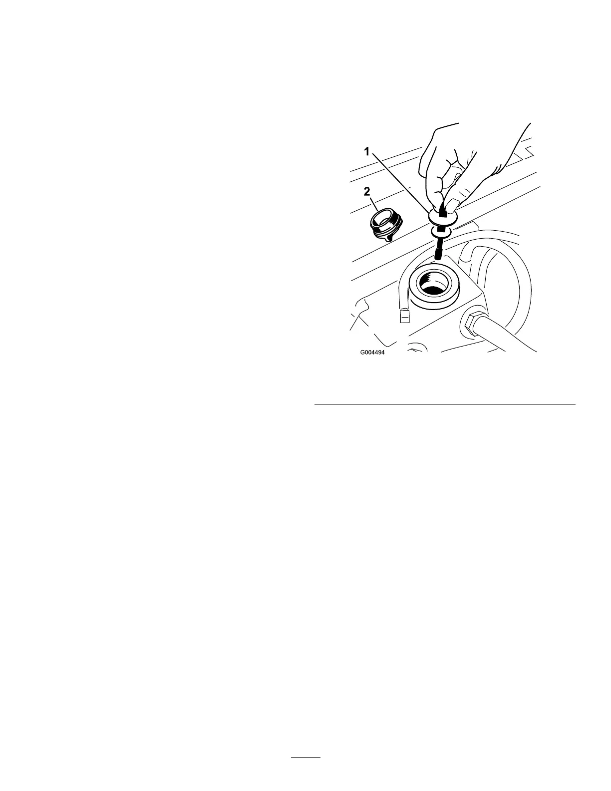
5.Removethehydraulicllcapfromthellerneck
(Figure92).
g004494
Figure92
1.Dipstick2.Fillcap
6.Removethedipstickandwipeitwithacleanrag
(Figure92).
7.Placethedipstickintothellerneck;then
removeitandcheckthelevelofuid(Figure92).
Note:Ifthelevelisnotwithinthenotchedarea
ofthedipstick,addenoughhigh-qualityhydraulic
uidtoraisetheleveltowithinthenotchedarea.
Important:Donotoverll.
8.Replacethedipstickandthreadthellcap
nger-tightontothellerneck.
9.Checkallhosesandttingsforleaks.
61

 Loading...


