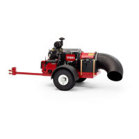
ProForce Debris Blower Page 4 − 9 Electrical System
Component Testing
For accurate resistance and/or continuity checks, elec-
trically disconnect the component being tested from the
circuit (e.g. unplug the switch connector before doing a
continuity check on switch).
CAUTION
When testing electrical components for continu-
ity with a multimeter (ohms setting), make sure
that power to the circuit has been disconnected.
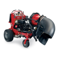
Ignition Switch
The engine mounted ignition (key) switch used on the
ProForce Debris Blower has three positions (OFF, RUN
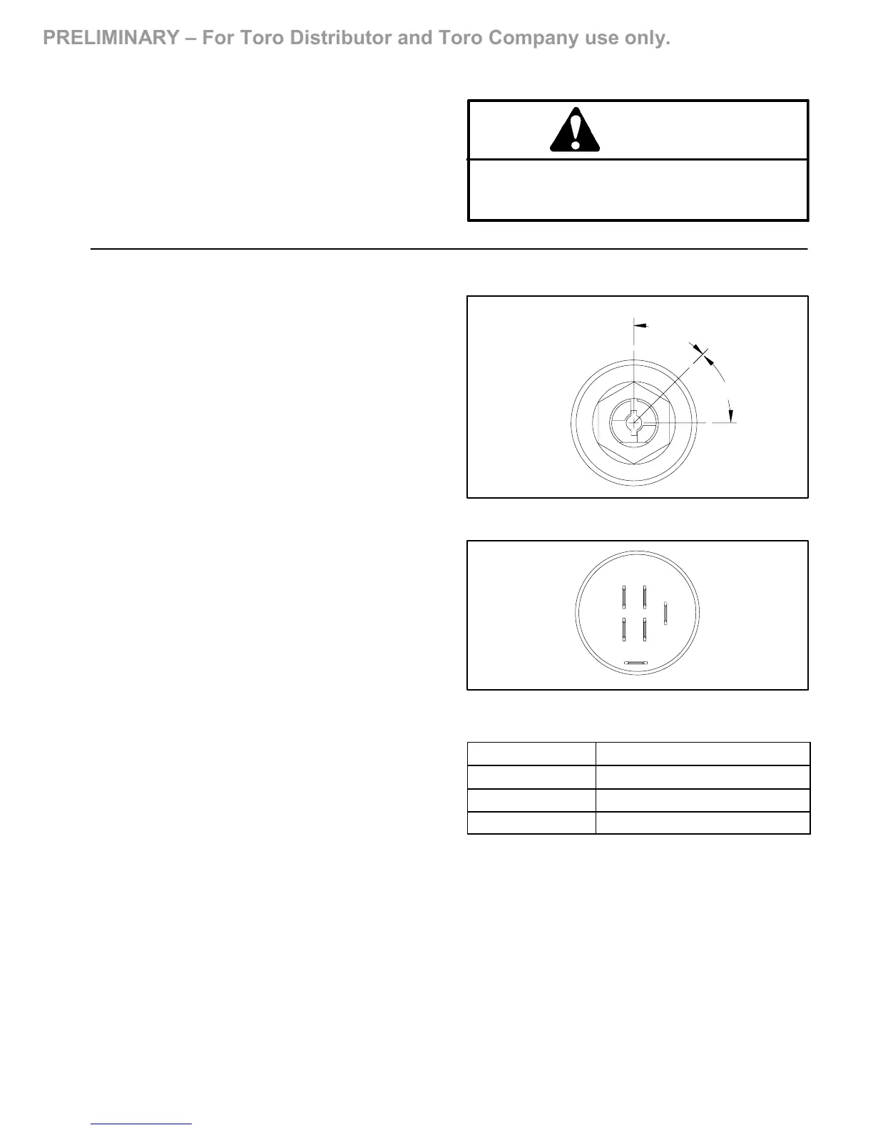
and START) (Fig. 5). The switch terminals are posi-
tioned as shown in Figure 6.
Testing
The circuitry of the ignition switch is shown in the chart
below. With the use of a multimeter (ohms setting), the
switch functions may be tested to determine whether
continuity exists between the various terminals for each
switch position.
Testing
1. Make sure that ignition switch is OFF.
2. To prevent unexpected machine operation, discon-
nect the negative battery cable from the battery termi-
nal. Position disconnected negative cable away from
the negative battery terminal.
3. Unplug wire harness connectors from switch.
4. The circuitry of the ignition switch is shown in the
chart in the right column. With the use of a multimeter
(ohms setting), the switch functions may be tested to de-
termine whether continuity exists between the various
terminals for each switch position.
5. Connect the harness connectors to the switch after
testing.
6. Connect negative battery cable to negative battery
terminal. Tighten nut that secures battery cable from 10
to 15 ft−lb (14 to 20 N−m). Make sure that battery cover
is secured.
Figure 5
45
45
RUN
START
OFF
o
o
G
L
B
S
M
A
Figure 6
POSITION
CIRCUIT
OFF G + M + A
RUN B + L + A
START B + L + S