AdjustingtheMotionControl
Levers
AdjustingtheHeight
Themotioncontrolleverscanbeadjustedhigheror
lowerformaximumoperatorcomfort.
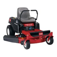
1.Removethe2boltsholdingthecontrollevertothe
controlarmshaft(
Figure23).
2.Movethecontrollevertothenextsetofholes.
Securetheleverwiththe2bolts(Figure23).
Figure23
1.Controlarmshaft3.Slotted,upperhole
2.Controllever
4.Bolt
3.Repeattheadjustmentfortheoppositecontrol
lever.
AdjustingtheTilt
Themotioncontrolleverscanbetiltedforeoraftfor
maximumoperatorcomfort.
1.Loosentheupperboltholdingthecontrolleverto
thecontrolarmshaft.
2.Loosenthelowerboltjustenoughtopivotthe
controlleverforeoraft(
Figure23).Tightenboth
boltstosecurethecontrolinthenewposition.
3.Repeattheadjustmentfortheoppositecontrol
lever.
PushingtheMachinebyHand
Important:Alwayspushthemachinebyhand.
Nevertowthemachinebecausedamagemay
occur.
Thismachinehasanelectricbrakemechanismandto
pushthemachinetheignitionkeyneedstobeinthe
Runposition.Thebatteryneedstobechargedand
functioningfortheelectricbraketobedisengage.
ToPushtheMachine
1.Parkthemachineonalevelsurfaceanddisengage
thebladecontrolswitch.
2.Movethemotioncontrolleversoutwardtopark
position,stoptheengine,andwaitforallmoving
partstostopbeforeleavingtheoperatingposition.
3.Raisetheseattolocatethebypassleversbehindthe
battery,ontheframe.
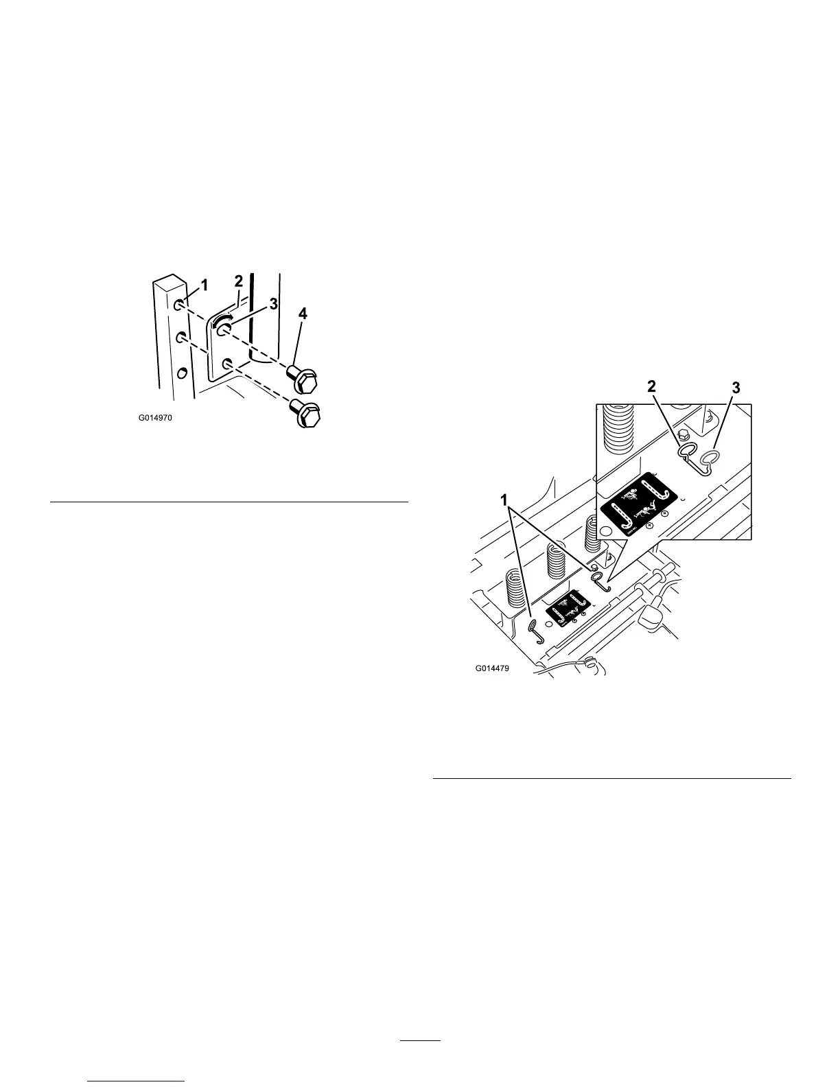
4.Movethebypassleversforwardsandthenout
tolocktheminplaceasshownin
Figure24to
disengagethewheelmotors.Repeatthisforeach
lever.
5.Lowertheseatandmovethemotioncontrollevers
inwardtotheneutralpositionandturntheignition
keytotherunposition.Donotstartthemachine.
Themachineisnowabletobepushedbyhand.
Figure24
1.Bypassleverlocations
3.Leverpositionforpushing
themachine
2.Leverpositionfor
operatingthemachine
6.Whennished,ensurethekeyhasbeenreturned
totheStoppositiontoavoiddrainingthebattery
charge.
Ifthemachinefailstomovetheelectricbrake
maystillbeengaged.Ifnecessarytheelectric
brakecanbereleasedmanually.Refertothe
ReleasingtheElectricBrake(page33)procedurein
DriveMaintenance.
21
 Loading...