Electrical System
Maintenance
2
8
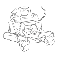
Figure 37
5
7 i
G014917
1. Tee Fitting, vent line 5. In-line Fuel filter
2. Emissions filter (certain 6. Flow direction arrow
models only)
3. Open port 7. Fuel line to engine
4. Fuel line from tank 8. Hose clamp
.
.
6.
Squeeze the ends of the hose clamps together and
slide them away from the filter (Figure 37).
Remove the filter from the fuel lines.
Install a new filter with the flow direction arrow
coming from the fuel tank and pointing to the
engine. Move the hose clamps close to the filter
(Figure 37) to secure it in place.
Servicing the Emissions Filter
Service Interval: Every i00 hours/Yearly (whichever
comes first)
Note: CARB compliant models are equipped with a
maintenance free emissions canister and do not have
an emissions filter to be serviced. This procedure will
not apply to these models.
Some machines are equipped with a emissions filter
(Figure 37) connected to a tee fitting on the vent line
coming from the gas tank. The filter has an ()pen port by
design. The filter should be inspected regularly Replace
the filter if the filter is dirty or clogged.
CALIFORNIA
Proposition 65 Warning
Battery posts, terminals, and related
accessories contain lead and lead compounds,
chemicals known to the State of California
to cause cancer and reproductive harm.
Wash hands after handling.
Charging the Battery
Removing the Battery
Battery terminals or metal tools could short against
metal machine components causing sparks. Sparks
can cause the battery gasses to explode, resulting
in personal injury.
• When removing or installing the battery, do not
allow the battery terminals to touch any metal
parts of the machine.
• Do not allow metal tools to short between
the battery terminals and metal parts of the
machine.
.
.
.
4.
Park the machine on a level surface and disengage
the blade control switch.
Move the motion control levers outward to the
park position, stop the engine, remove the ke), and
wait for all moving parts to stop before leaving the
operating position.
Raise the seat to access the battery.
Disconnect the negative (black) ground cable from
the battery post (Figure 38). Retain all fasteners.
34

 Loading...