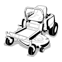
Figure 41
42 inch leveler bracket shown
1. Hairpin cotter and washer 3. Front hole
2. Leveling bracket 4. Rear hole
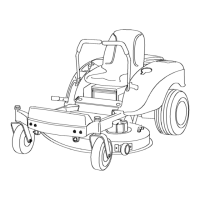
Figure 42
38 inch leveler bracket shown
1. Hairpin cotter and washer 3. Front hole
2. Leveling bracket 4. Rear hole
8. Chec k the front-to-rear blade slope; refer to
Adjusting the F ront-to-R ear Blade Slope .
Adjusting the Front-to-Rear
Blade Slope
Chec k the front-to-rear blade lev el any time y ou
install the mo w er . If the front of the mo w er is
more than 5/16 inc h (7.9 mm) lo w er than the
rear of the mo w er , adjust the blade lev el using the
follo wing instr uctions:
1. P ark the mac hine on a lev el surface and
diseng ag e the blade control switc h.
2. Mo v e the motion control lev ers to the brak e
position, stop the engine , remo v e the k ey , and
w ait for all mo ving par ts to stop before lea ving
the operating position.
3. Chec k the air pressure of all four tires . If
needed, adjust to the recommended inflation;
refer to Chec king the Tire Pressure in
Dri v e System Maintenance , pag e 29 .
4. Chec k and adjust the side-to-side blade lev el
if y ou ha v e not c hec k ed the setting; refer to
Lev eling the Mo w er from Side-to-Side .
5. Measure the length of the rod extending out of
the adjusting bloc k on the sides of the c hassis
( Figure 43 ).
6. If the rod length is not a 3/4 inc h (19 mm),
remo v e the hair pin cotter and w asher from the
end of the adjusting rod ( Figure 43 ) and tur n
the rod until the 3/4 inc h (19 mm) dimension
is obtained.
7. Install the end of the rod into the hole in the
mo w er mount and secure it with the w asher
and hair pin cotter .
Figure 43
38 inch leveler bracket shown
1. Leveling bracket 3. Adjusting rod
2. Adjusting block 4. Hairpin cotter and washer
8. R e peat ste ps 5 through 7 for the opposite side
of the mo w er .
9. Set the height-of-cut at position D [3 inc h
(76 mm)] and carefully rotate the blades so
they are facing front to rear ( Figure 44 ).
10. Measure from the tip of the front blade to the
flat surface and the tip of the rear blade to the
flat surface ( Figure 44 ). If the front blade tip
is not 1/16-5/16 inc h (1.6-7.9 mm) lo w er than
the rear blade tip , adjust the front loc kn uts .
32
 Loading...