2.Parkthemachinesothatthedrainsideisslightly
lowerthantheoppositesidetoassuretheoildrains
completely.
3.Disengagethebladecontrolswitchandmovethe
motioncontrolsoutwardtotheparkposition.
4.Stoptheengine,removethekey,andwaitforall
movingpartstostopbeforeleavingtheoperating
position.
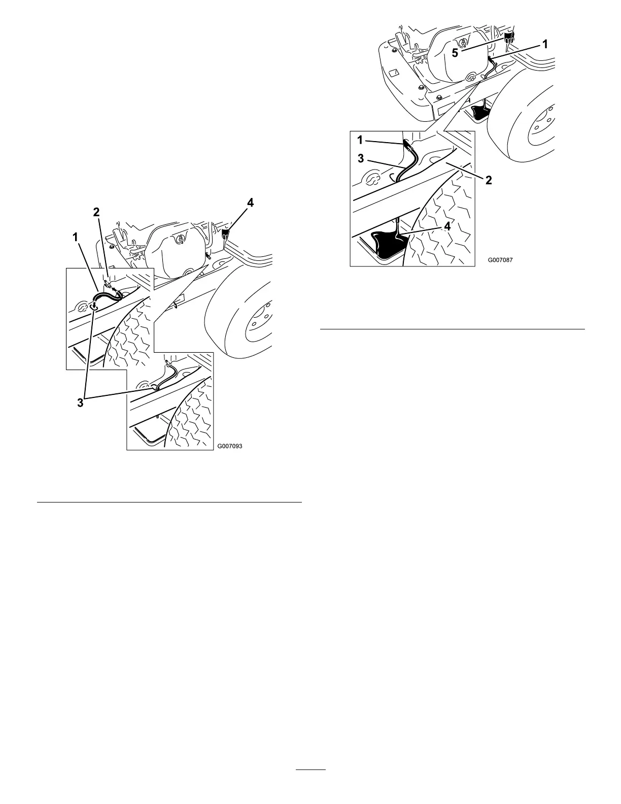
5.Cleantheareaaroundthedrainvalveandonthe
machineframe.Locatetheoildrainhoseandslide
itoverthedrainvalve(Figure32).
Figure32
1.Oildrainhose3.Holeinframe
2.Drainvalve
4.Oillter
6.Placetheoppositeendoftheoildrainhosethrough
thedrainholeintheframe(Figure32).
7.Placeapanunderneathmachinedirectlybelowthe
drainholeintheframeasshowninFigure33.
Figure33
1.Oildrainvalve
4.Pan
2.Machineframe5.Oillter
3.Oildrainhose
8.Turnthedrainvalve1/4counterclockwisetoopen
andallowtheoiltodrain(Figure33).Removethe
oilllcap/dipstick(Figure31).
9.Besuretoallowampletimeforcompletedrainage.
10.Removetheoldlterandwipeoffthemountingpad
(Figure33).
11.Whenoilhasdrainedcompletely,closetheoildrain
valve.Removetheoildrainhoseandwipeupany
excessoilontheframe(Figure33).
Note:Disposeoftheusedoilatarecyclingcenter.
12.Placethenewreplacementlterinashallowpan
withtheopenendup.Pournewoiloftheproper
type,inthroughthethreadedcenterhole.Stop
pouringwhentheoilreachesthebottomofthe
threads.Allowaminuteortwofortheoiltobe
absorbedbytheltermaterial.
13.Applyathinlmofcleanoiltotherubbergasketon
thenewlter.
14.Installthereplacementoilltertothemountingpad.
Turntheoillterclockwiseuntiltherubbergasket
contactsthepad,thentightenthelteranadditional
2/3to1turn(Figure34).
30
 Loading...