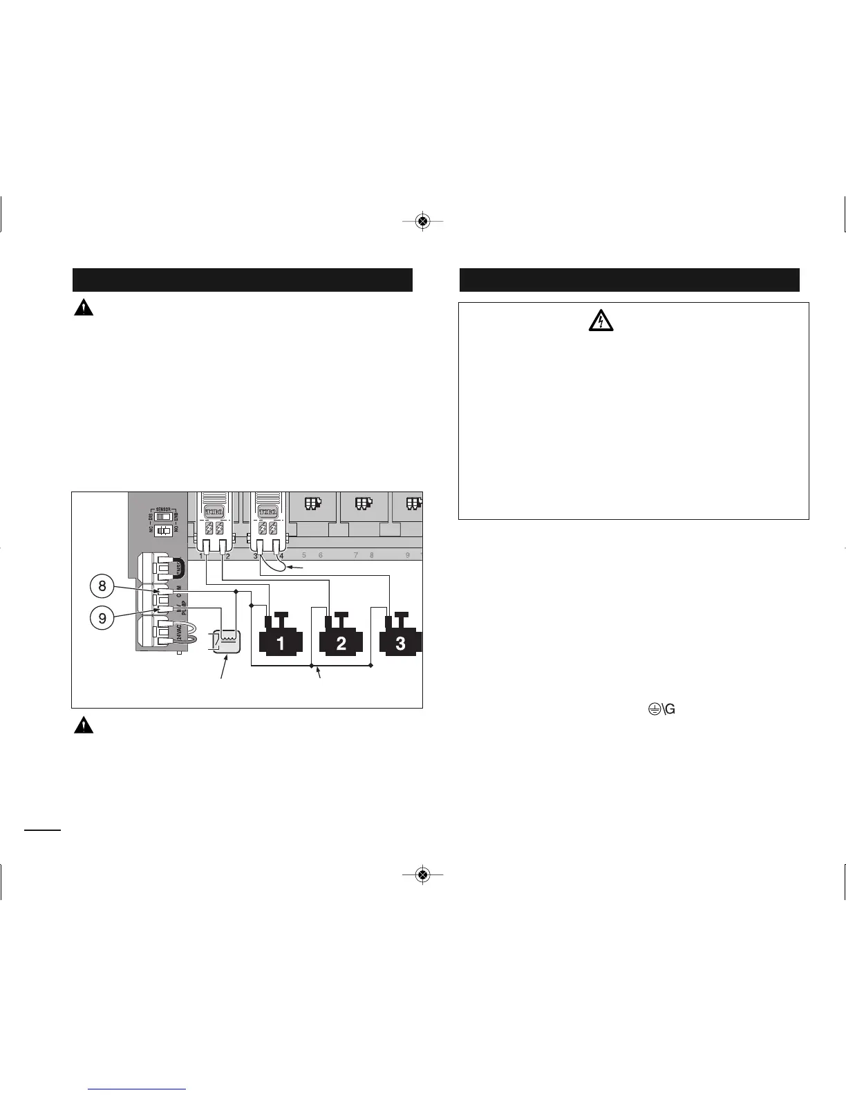
CAUTION: To prevent controller damage, never
connect an auxiliary pump starter directly to the
controller’s 24 VAC output. A 24 VAC 0.50A relay,
must be used to connect the controller to the pump
starter circuit.
+AGF73I;D7B3;D8DA?F:7BG?BD7>3K;@FAF:7
5A@FDA>>7D:AGE;@9
A@@75FA@7I;D7FAF:7F7D?;@3>>347>76(&
A@@75FF:7D7?3;@;@9I;D7FAF:7F7D?;@3>>347>76
).&)&/3EE:AI@47>AI
CAUTION: To prevent pump damage due to
prolonged dead-head pressure, connect a jumper wire
from an unused station terminal to a terminal with a
with a valve connected.
Note: +787DFAR)G?BA@FDA>3@607>>+75AH7DKSE75F;A@
A@B3978AD;?BADF3@FBG?B5;D5G;F5A@FDA>;@8AD?3F;A@
+AGF7F:7BAI7D3@67CG;B?7@F9DAG@6I;D7E8DA?
F:7BAI7DEAGD57F:DAG9:F:75A@6G;F3@6;@FAF:7
5A@FDA>>7DFD3@E8AD?7D5A?B3DF?7@F
Note: -:75A@FDA>>7DF7D?;@3>4>A5=3557BFEI;D7E;L7
GBFA0!??
+7?AH7??;@EG>3F;A@8DA?F:7I;D77@6E
.E;@93E?3>>8>3F4>367E5D7I6D;H7DE75GD7F:7I;D7E
3EE:AI@FAF:7F7D?;@3>4>A5=3E8A>>AIE
Line ADLine 1 %FALNeutral ADLine 2 %FAN
3@6Equipment Ground FA
#@EF3>>3@6E75GD7F:7FD3@E8AD?7D5A?B3DF?7@F5AH7D
BB>KBAI7DFAF:75A@FDA>>7D
Note: -:76;EB>3KI;>>479;@8>3E:;@93?)D7EE
3@K4GFFA@FAEFABF:76;EB>3K8DA?8>3E:;@9
Connecting the Power SourceConnecting a Pump Start Relay
12
Pump Start Relay
Valve Common Wire
Jumper Wire
WARNING
AC power wiring must be installed and connected
by qualified personnel only. All electrical compo-
nents and installation procedures must comply
with all applicable local and national electrical
codes. Some codes may require a means of discon-
nection from the AC power source installed in the
fixed wiring and having a contact separation of at
least 0.120" (3mm) in the line and neutral poles.
Make sure the power source is OFF prior to con-
necting the controller.
-&.!-&A5&)397