station it controls. You will need to have this information available when
connecting the valve wires to the controller.
4. Secure all wire splices using twist-on wire connectors. To prevent corrosion
and possible short circuits, use a grease cap or similar waterproofing method
to insulate each connection.
5. Route the wire cable into the controller through the opened 3/4" (19mm)
access hole in the base of the housing or through the PVC conduit if it is
installed. Strip insulation back 1/2" (13mm) from all cable wires.
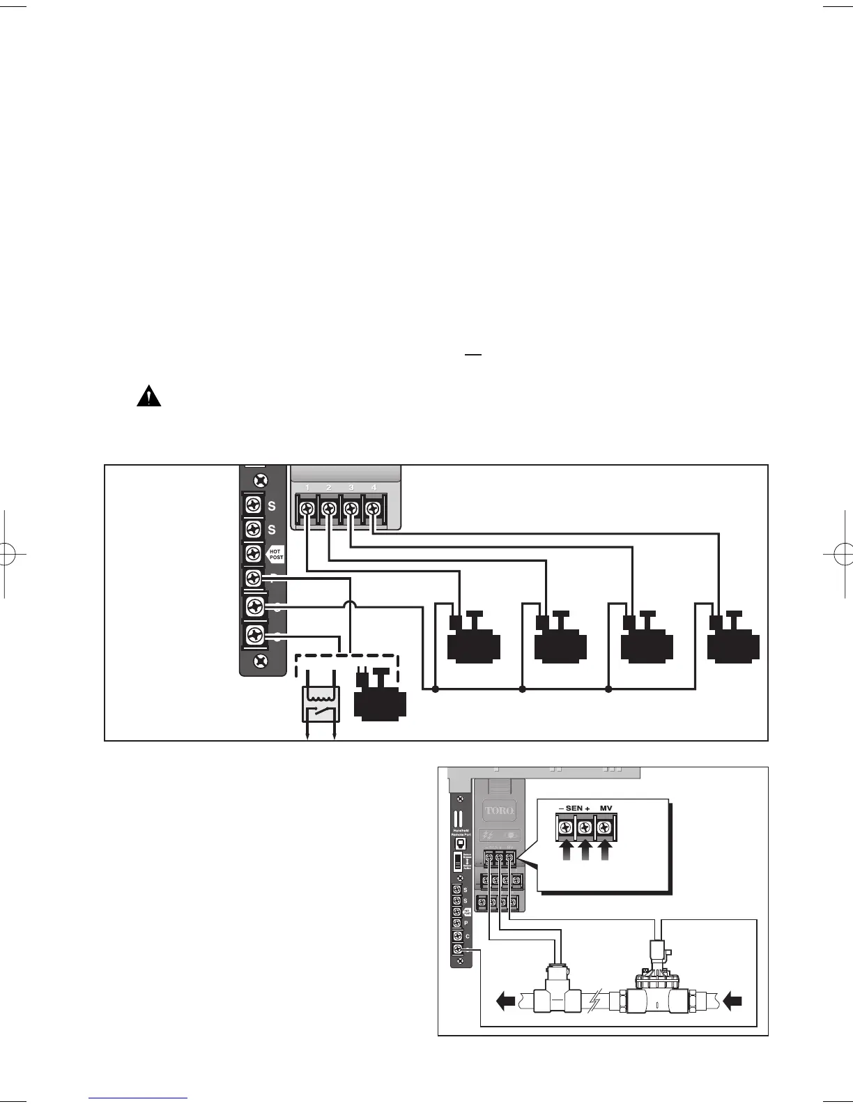
6. Secure the valve common wire to the PCB terminal labeled C (common).
Connect the individual station valve wires to the appropriate station module
terminals.
7. Connect one wire from the master valve or pump start relay to the PCB
terminal labeled PUMP/MV.
CAUTION: Never connect an auxiliary pump starter directly to the
controller. A 24V, 0.5A (max) relay must be used to connect the controller to
the pump starter circuit.
Flow Sensor Connection
1. Route the flow sensor wires into
the controller cabinet.
2. Connect the sensor wires to the
control module terminal block as
follows: Black to negative (–) and
Red to positive (+).
Note: Sensor wires must be
installed in the correct polarity to
enable operation.
(continued)
21
1
MV
234
Black
Wire
Red
Wire
Master Valve
Wire