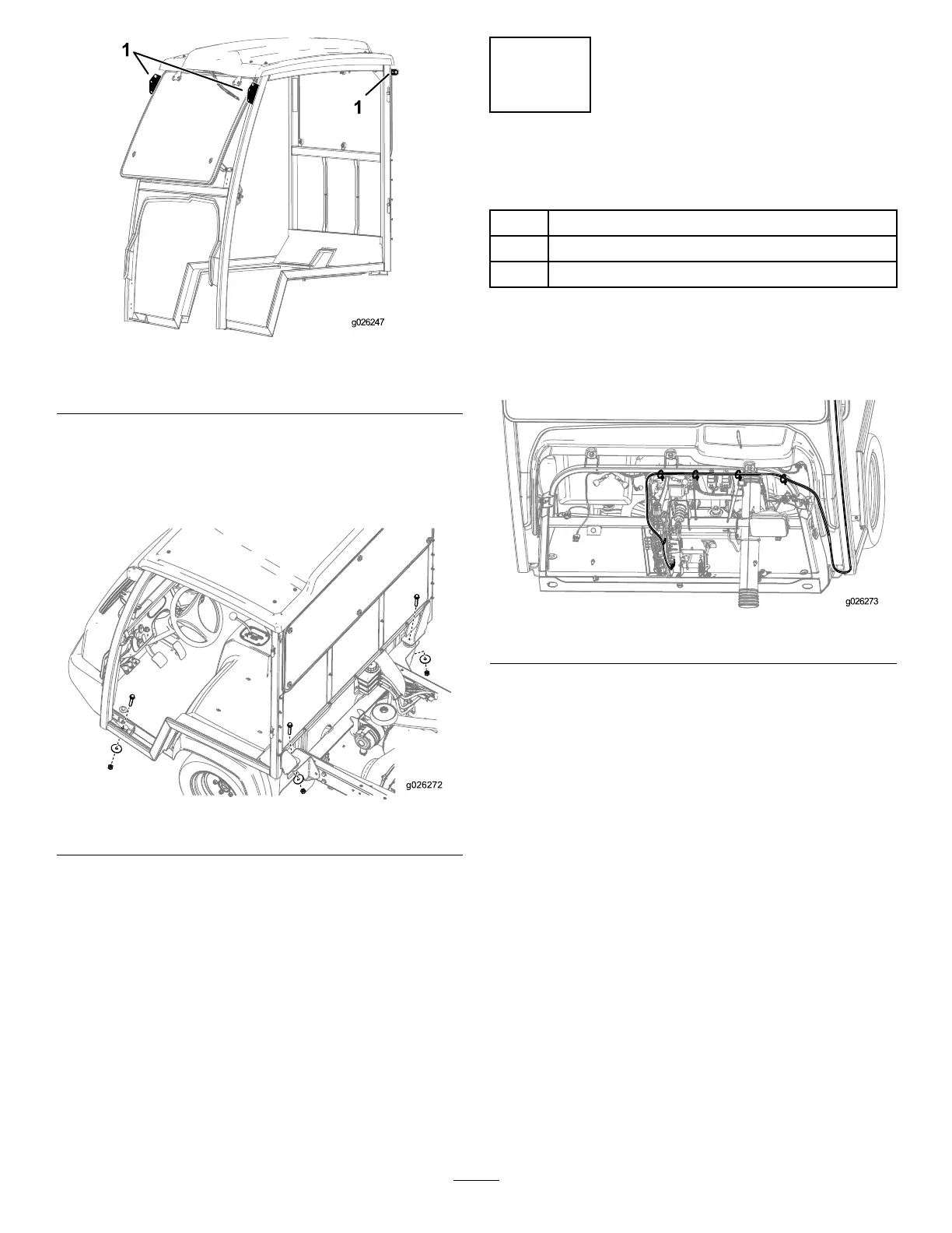
g026247
Figure 31
1. Lifting points
6. Secure the frame to the machine using the 4
bolts (1/2 inch), 4 washers (1/2 inch), and 4 nuts
(1/2 inch) as shown in Figure 32 .
Note: Do not tighten the 4 bolts (1/2 inch).
g026272
Figure 32
7. Adjust the cab from side to side to ensure that
the cab is centered.
Use the adjuster bolt ( Figure 26 ) to center the
cab.
8. T orque the 4 bolts (1/2 inch) to 91 to 1 13 N∙m
(67 to 83 ft-lb).
10
Routing the W ire Harness
Parts needed for this procedure:
1 Wire harness
4
Cable ties
1
Fuse (30 A)
Procedure
1. Route the wire harness as shown in Figure 33
and secure it with the 4 cable ties.
g026273
Figure 33
2. Connect the ring terminal on the harness to
the grounding block and insert the fuse-block
connector into an available fuse-block
connection ( Figure 34 ).
Note: If there is not an available fuse-block
connection, you must add a fuse block to the
fuse-block grouping. Contact your Authorized
Service Dealer for more information.
14

 Loading...


