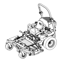
Figure79
1.Measureherefromblade
tohardsurface
2.MeasureatBandC
2.MeasuretherightbladeattheBlocation,froma
levelsurfacetothecuttingedgeofthebladetip
(Figure79).
3.Recordthismeasurement.Thismeasurementneeds
tobe3-1/8to3-1/4inches.
4.Positiontheleftbladeside-to-side(Figure79).
5.MeasuretheleftbladeattheClocation(Figure79),
fromalevelsurfacetothecuttingedgeoftheblade
tip.
6.Recordthismeasurement.Thismeasurementneeds
tobe3-1/8to3-1/4inches(80to83mm).
7.IfthemeasurementsatpositionsBorCarenot
correct,loosentheboltattachingtherearchainto
therearsupportarm(Figure80).
Figure80
1.Rearchain5.Adjustmentbolt
2.Rearsupportarm6.Frontswivel
3.Bolt7.Frontsupportarm
4.JamNut
8.Loosenthejamnutundertherearsupportarmand
adjusttheadjustmentbolttogetameasurementof
3-1/8to3-1/4inches(80to83mm)(Figure80).
Note:Itisrecommendedthatbothsidesofthe
mowerareadjustedthesamedistance.
9.Tightenthejamnutundertherearsupportarm
andtightentheboltsecuringthechaintotherear
supportarm.
10.Adjusttheoppositesideifneeded.
AdjustingtheFront-to-RearMower
Pitch
1.Positiontherightbladefront-to-rear(Figure81).
Figure81
1.Measureherefromblade
tohardsurface
2.MeasureatAandB
2.MeasuretherightbladeattheAlocation,froma
levelsurfacetothecuttingedgeofthebladetip
(Figure81).
3.Recordthismeasurement.
4.MeasuretherightbladeattheBlocation,froma
levelsurfacetothecuttingedgeofthebladetip
(Figure81).
5.Recordthismeasurement.
6.Themowerbladeshouldbea1/4to3/8inch
(6to10mm)loweratpositionAthanatposition
B(Figure81).Ifitisnotcorrect,proceedtothe
followingsteps.
Note:Bothofthefrontswivelsneedtobeadjusted
thesameamounttomaintainequalchaintension.
7.Loosenthefrontswiveljamnuts,atthefrontof
therightandleftswivels,approximatelya1/2inch
(13mm)(Figure80).
56

 Loading...


