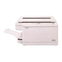
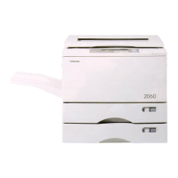
Do you have a question about the Toshiba 1550 and is the answer not in the manual?
Procedures for safely transporting and installing the copier unit.
Guidelines for proper installation, including power and placement requirements.
Safety precautions and best practices to follow during machine servicing.
Detailed technical specifications for the 1550 and 1560 copier models.
Lists optional accessories available for the copier, with part numbers.
Details available options and consumable supplies for the copier model.
Visual diagrams showing sectional views and location of electrical parts within the machine.
Identifies the location of various electrical components within the machine's circuitry.
Step-by-step instructions for removing various external covers of the machine.
Procedures for removing and installing specific electrical components like PC boards and motors.
Explains the step-by-step process of how the copier creates an image.
Details the specific copying process steps and components for models ED-1550/1560.
Provides a general overview of the copier's operational modes and functions.
Explains the operational sequences for warm-up, standby, and various copying modes.
Describes how faults are detected and indicated, and their classification.
Presents flowcharts illustrating operational sequences and fault handling logic.
Details the components and functions of the copier's control panel and display.
Explains the meaning of various symbols and indicators shown on the control panel.
Maps machine conditions to the corresponding operator actions and key functionalities.
Explains the mechanical construction and layout of the copier's drive system.
Details the functions of the various drive components and their roles.
Provides instructions for disassembling and replacing key drive mechanism parts.
Describes the physical layout and components of the copier's optical system.
Explains how the scanning, mirror, and lens motors operate the optical system.
Provides procedures for removing and replacing components within the optical system.
Details the mechanical construction of the upper and lower paper feeder units.
Details the paper feeding operations and jam detection/clearing procedures.
Provides instructions for disassembling and replacing parts of the paper feeder unit.
Describes the physical construction of the drum and related components.
Explains the functions of the main charger, discharge lamp, and transfer/separation chargers.
Provides procedures for disassembling and replacing drum-related components.
Details the mechanical construction of the developer unit.
Explains the drive system for the magnetic roller, mixers, and toner cartridge.
Provides instructions for disassembling and replacing developer unit components.
Describes the physical construction of the cleaner unit.
Explains the functions of the main blade, recovery blade, and toner recovery auger.
Provides procedures for disassembling and replacing cleaner unit components.
Details the construction of the fuser and paper exit sections, including rollers and lamps.
Explains the operation of the fuser unit for fixing toner and the paper exit section.
Provides procedures for disassembling and replacing components of the fuser and paper exit sections.
Lists the technical specifications for the optional paper feeding unit MY-1004.
Provides a general overview and identifies the main components of the paper feeding unit.
Explains the paper feeding operations and jam detection/clearing procedures.
Details procedures for disassembling and replacing covers and parts of the paper feeding unit.
Detailed logic circuit diagram for the 1550 model, showing PWA-F-LGC connections.
Shows the circuit diagram for the control panel (PWA-F-PNL) of the copier.
Illustrates the power supply circuit diagram, detailing DC and AC outputs.
Shows the physical layout of the PWA-F-LGC PC board.
Shows the physical layout of the PWA-F-FUS PC board.
Shows the physical layout of the PWA-F-PNL PC board.
Shows the physical layout of the PWA-F-AES PC board.
Shows the physical layout of the PWA-F-LRG PC board.
Illustrates the harness connections for the AC control circuit of the copier.
Shows the DC harness connections for the 1550 model, listing component symbols.
Step-by-step guide for unpacking and setting up the 1550 model copier.
Details the procedure for automatically adjusting the auto-toner sensor.
Outlines checks to perform after setup to ensure proper operation and image quality.
Explains how to adjust light distribution for optimal image quality.
Guides users on manually adjusting exposure settings for the 100% reproduction ratio.
Describes the automatic process for adjusting exposure across multiple reproduction ratios.
Provides manual adjustment procedures for exposure based on specific codes and modes.
Instructions on how to change the paper size settings within the cassette.
Step-by-step guide for safely installing a new toner cartridge into the copier.
Instructions for unpacking and setting up the optional paper feeding unit MY-1004.


 Loading...