1550/1560 GENERAL 2 - 19 Mar. 1998 © TOSHIBA
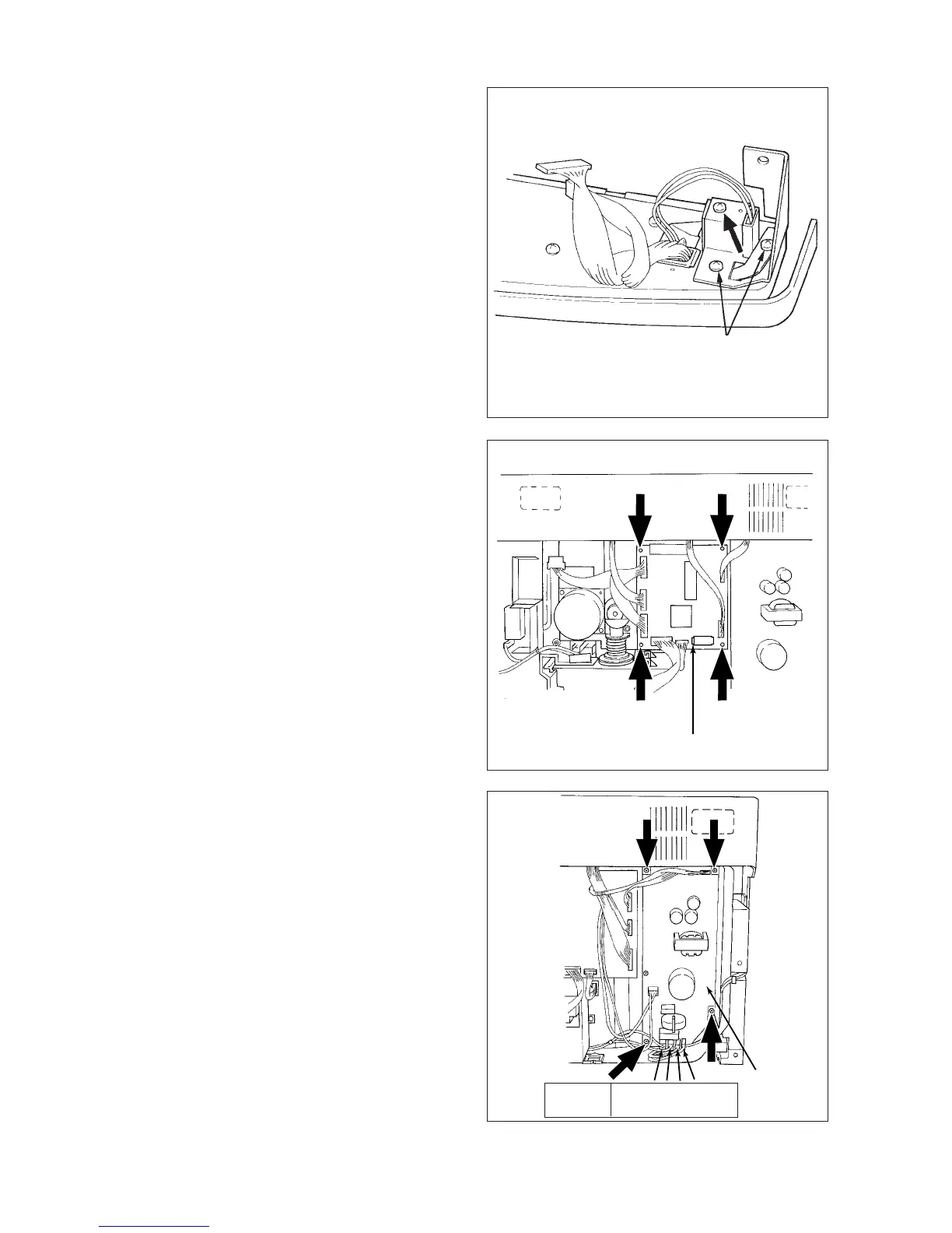
[B] Total counter
(1) Remove the control panel cover.
(2) Place the control panel cover upside down and
remove the two screws fastening the bracket.
(3) Remove one screw.
(4) Disconnect one connector.
Note: Be careful not to allow the ground wire of
the shield to be cut.
[C] Logic PC board (PWA-F-LGC)
(1) Remove the rear cover.
(2) Disconnect connectors (10 pcs. when no op-
tional equipment is used and 11 pcs. when op-
tional equipment are used) and take out the PC
board from its four lock supports.
[D] Power supply unit
(1) Remove the rear cover.
(2) Disconnect connectors (9 pcs.).
(3) Remove four screws.
* About bottom 4 connectors, black harness
must be connected “L” terminal that is de-
scribed on PC board and white must be “N”.
PWA-F-LGC
Screws fastening the bracket
PS-ACC
Harness
color
*
Black White
Black
White
 Loading...