44
7. APPLIED CONTROL AND FUNCTION
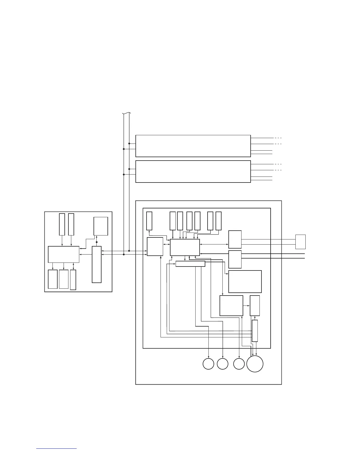
7-1. Indoor Controller Block Diagram
7-1-1. When Main (Simple) Wired Remote Controller Connected
4-Way Cassette Type
Indoor control P.C. board (MCC-1570)
Indoor unit
Main (Simple) wired remote controller (up to 2 units)
Power
supply
circuit
Function setting
Key switch
EEPROM
Power supply circuit
DC5V
MCU
EEPROM
HA
Remote controller
communication circuit
Display
LCD
MCU
MCU
External output
280V
DC
DC5V
DC12V
DC20V
PMV
AB A B AB
×4
Indoor/outdoor communication
L1
U1
U1
U2
U2
L2
L1
L1
L2
L2
U1
U2
U1
U2
Display
LED
Remote
controller
communication
circuit
Louver
motor
Drain
pump
Indoor
fan
motor
Fan motor
control circuit
In operation
Alarm
Getting ready
Thermostat ON
COOL
HEAT
FAN
Driver
TA sensor
TCI sensor
TC2 sensor
TCJ sensor
Float input
AC
synchronization
signal input circuit
BUS
communication
circuit
Outdoor
unit
Outdoor
unit
Outdoor
unit
Power source
208/230-1-60
Power
source
Power
source
Sameas left Sameas left
Up to 8 units can be
connected.
#2 #3
#1
 Loading...