–8–
EN
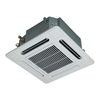
• After the electric work has finished, pour water
during COOL mode operation.
• If the electric work has not yet finished, pull out the
float switch connector (CN34: Red) from the
electrical control box, and check draining by plugging
the single phase 208/230 V power to the terminal
blocks L
1 and L2.
If doing so, the drain pump motor operates.
• Test water drain while checking the operation sound
of the drain pump motor.
(If the operation sound changes from continuous
sound to intermittent sound, water is normally
drained.)
After the check, the drain pump motor runs,
connecting the float switch connector.
(In case of check by pulling out the float switch
connector, be sure to return the connector to the
original position.)
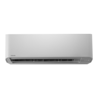
Perform heat insulating
• As shown in the figure, cover the flexible hose and
hose band with the attached heat insulator up to the
bottom of the indoor unit without gap.
• Cover the drain pipe seamlessly with a heat insulator
to be procured locally so that it overlaps with the
attached heat insulator of the drain connecting
section.
* Direct the slits and seams of the heat insulator
upward to avoid water leakage.
Air discharge
area
Insert the leading part of the hose
between the heat exchanger and
the drain pan, and then bend it
downward.
Polyethylene hand
pump for pouring
water in drain pan
Water (0.4-0.5 gal
(1500 cc to 2000 cc))
Vessel
Drain pan
Pull out connector CN34 (Red)
from P.C. board.
CN34
(RED)
Black
Black
Red
White
Power
terminals
208/230-1-60
Wrap the attached heat insulator seamlessly from
the surface of the indoor unit.
Flexible hose
Hose band
Attached heat
insulator
Heat insulator to be
procured locally
Hard vinyl chloride pipe
6 Refrigerant piping and evacuation
Refrigerant piping
1. Use copper pipe with 0.03” (0.8 mm) or more
thickness.
2. Flare nut and flare works are also different from
those of the conventional refrigerant.
Take out the flare nut attached to the main unit of the
air conditioner, and use it.
When the refrigerant pipe is long, provide support
brackets at intervals of 8’2” - 9’10” (2.5 - 3 m) to clamp
the refrigerant pipe. Otherwise, abnormal sound may be
generated.
IMPORTANT 4 POINTS FOR PIPING WORK
1. Remove dust and moisture from the inside of the
connecting pipes.
2. Tight connection (between pipes and unit)
3. Evacuate the air in the connecting pipes by using
VACUUM PUMP.
4. Check the gas leakage. (Connected points)
Pipe size
Permissible piping length and
height difference
They vary according to the outdoor unit.
For details, refer to the Installation Manual attached to
the outdoor unit.
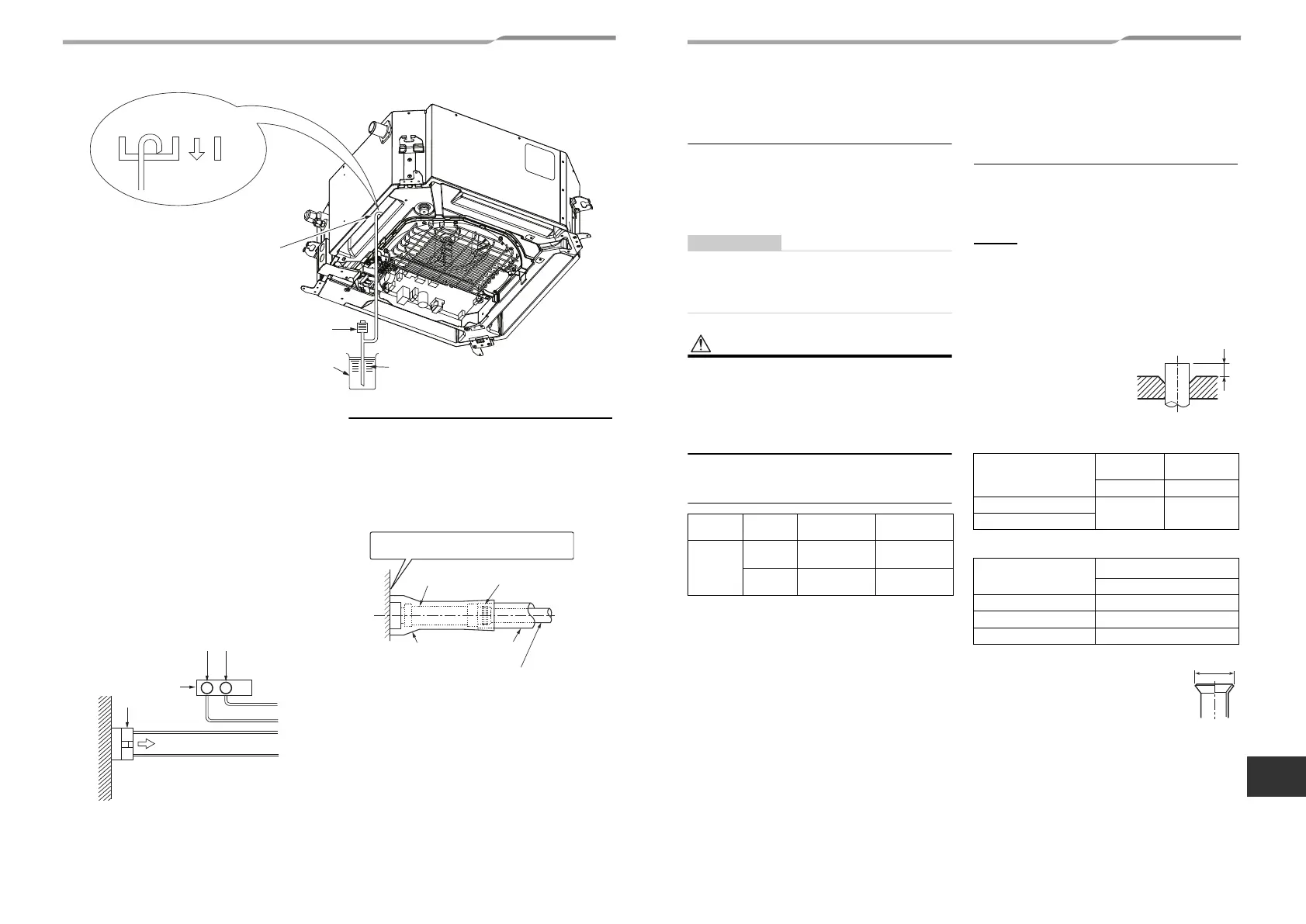
Flaring
• Cut the pipe with a pipe cutter.
Remove burrs completely.
Remaining burrs may cause gas leakage.
• Insert a flare nut into the pipe, and flare the pipe.
As the flaring sizes of R410A differ from those of
refrigerant R22, the flare tools newly manufactured
for R410A are recommended.
However, the conventional
tools can be used by adjusting
projection margin of the
copper pipe.
▼ Projection margin in
flaring: B (Unit: in (mm))
Rigid (Clutch type)
▼ Flaring dia. meter size: A (Unit: in (mm))
* In case of flaring for R410A with the
conventional flare tool, pull it out approx.
0.02" (0.5 mm) more than that for R22 to
adjust to the specified flare size.
The copper pipe gauge is useful for
adjusting projection margin size.
Model
name
MMU-
AP007, AP009,
AP012 type
AP015, AP018
type
Pipe size
Gas side
3/8”
(9.5 mm)
1/2”
(12.7 mm)
Liquid side
1/4”
(6.4 mm)
1/4”
(6.4 mm)
Outer dia. of copper pipe
R410A tool
used
Conventional
tool used
R410A R410A
1/4” (6.4), 3/8” (9.5)
0 - 0.02”
(0 - 0.5)
0.04” - 0.06”
(1.0 - 1.5)
1/2” (12.7)
Outer dia. of copper pipe
A
+0
–0.02 (0.4)
R410A
1/4” (6.4) 0.36” (9.1)
3/8” (9.5) 0.52” (13.2)
1/2” (12.7) 0.65” (16.6)
15-EN 16-EN
+00EH99876101-2_00Ta.book Page 8 Monday, September 1, 2014 10:15 AM
 Loading...