–23–
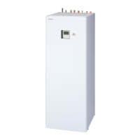
Hydro Unit
Installation Manual
Electrical connection to hydro unit
• Remove the front cover and the electrical box cover
from the Hydro Unit.
• The Hydro Unit power cable must be sized in
accordance with refer to “Electrical supply/cable
specifications”.
• Connect the Hydro Unit power cable to Terminal 02
as shown below.
• Ensure the Hydro Unit power cable is secured using
the cable clamp fitted in the electrical box.
• Ensure the Hydro Unit power cable connection
terminals are tight.
Outdoor unit to hydro unit electrical
connection
▼ Fig. 7-22
• Ensure electrical circuits are isolated before
commencing work.
• The Outdoor Unit to Hydro Unit interconnecting
cable must be sized in accordance with refer to
“Electrical supply/cable specifications”.
• Connect the Outdoor Unit to Hydro Unit
interconnecting cable as shown in the diagram
above.
• Ensure the Outdoor Unit to Hydro Unit
interconnecting cable is secured using the cable
clamp fitted in the electrical box.
• Ensure the Outdoor Unit to Hydro Unit
interconnecting cable connection terminals are tight.
▼ Fig. 7-21
Leakage
breaker
30 mA
Leakage
breaker
30 mA
Input power
220-230 V
50 Hz
Backup heater
220-230 V ~ type
(3 kW type)
Backup heater
380-400 V 3N~
type
(6,9 kW type)
Input power
220-230 V
3N~ 50 Hz
Leakage
breaker
30 mA
Input
power
220-230 V
~ 50 Hz
Input
power
380-400 V
3N~
50 Hz
Leakage
breaker
30 mA
Outdoor unit Hydro unit
23-EN
 Loading...