Do you have a question about the Toshiba RAS-137SKV-E5 and is the answer not in the manual?
| Type | Split System |
|---|---|
| Refrigerant | R410A |
| Power Supply | 220-240V, 50Hz |
| Energy Efficiency Ratio (EER) | 3.21 |
| Coefficient of Performance (COP) | 3.61 |
| Outdoor Unit Dimensions (HxWxD) | 550x780x290 mm |
| Indoor Unit Weight | 9 kg |
| Noise Level (Outdoor) | 50 dB(A) |
| Indoor Unit Dimensions (HxWxD) | 275 x 790 x 205 mm |
| Noise Level (Indoor) | 42 dB(A) |
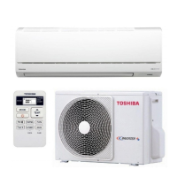
Details specifications for indoor and outdoor units across various models.
Provides further specification details for different unit models.
Outlines crucial safety precautions for handling R410A refrigerant during installation and servicing.
Specifies required piping materials and correct joint types for R410A systems.
Lists specialized tools required for R410A refrigerant handling and installation.
Details the procedure for recharging refrigerant in the air conditioning system.
Explains methods and materials for brazing refrigerant pipes.
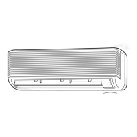
Provides detailed diagrams and dimensions of the indoor unit's components.
Presents diagrams and dimensions for the outdoor unit and its parts.
Lists electrical components and their specifications for the indoor unit.
Lists electrical components and their specifications for the outdoor unit.
Illustrates the refrigerant flow path for cooling and heating operations.
Presents operational data for various conditions, including temperatures and pressures.
Shows the control logic and signal flow for the indoor unit.
Details control logic and components of the outdoor unit's inverter assembly.
Provides an overview of the air conditioner's control system and main functions.
Explains various operating modes and control functions of the air conditioner.
Describes how to set and use the auto restart feature after power failure.
Details the parts and functions of the remote controller for operating the unit.
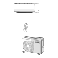
Illustrates physical layout and connection points for indoor and outdoor unit installation.
Covers optional installation parts and general installation guidelines.
Provides specific procedures for installing the indoor unit.
Provides specific procedures for installing the outdoor unit.
Covers miscellaneous installation topics like gas leak testing and remote control settings.
Initial checks to perform before detailed troubleshooting.
Basic judgment methods to identify the cause of a trouble.
Interpreting indoor unit LED indicators for self-diagnosis.
Using the remote controller to perform self-diagnosis and read error codes.
Troubleshooting procedures based on observed symptoms of the unit.
Simple checks for common main parts to diagnose issues.
Specific diagnostic steps for problems related to the outdoor unit.
A simplified method to test the outdoor fan motor's functionality.
Procedure to cancel the clean operation setting.
Step-by-step guide for replacing main parts within the indoor unit.
Instructions for replacing the microcomputer unit.
Step-by-step guide for replacing main parts within the outdoor unit.
Exploded view and parts list for the indoor unit (Part-E).
Exploded view and parts list for the indoor unit.
Exploded view and parts list for the outdoor unit (specific models).
Exploded view and parts list for the outdoor unit (specific model).
Exploded view and parts list for the outdoor unit (Part-E).