Do you have a question about the Toshiba RAS-13NAV-A and is the answer not in the manual?
Detailed operational and physical specifications for indoor and outdoor units.
Graphs showing current vs. compressor speed for cooling and heating.
Charts illustrating capacity changes based on outdoor temperature.
Crucial safety precautions for handling R410A refrigerant.
Guidelines for selecting and preparing copper pipes and joints for R410A.
List of specialized and general tools required for R410A systems.
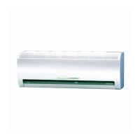
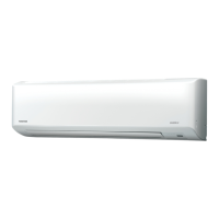
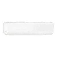
Diagrams showing the dimensions and parts of the indoor unit.
Diagrams illustrating the dimensions and external features of the outdoor unit.
Electrical schematic for the indoor unit of the 13NKV model.
Electrical schematic for the indoor unit of the 16NKV model.
Electrical schematic for the outdoor unit's inverter assembly.
List and specifications of electrical components for the 13NKV indoor unit.
List and specifications of electrical components for the 13NAV outdoor unit.
Schematic illustrating the refrigerant flow for the 13 series units.
Table of operating parameters for cooling and heating modes.
Block diagram showing the control functions of the indoor unit.
Block diagram detailing the control logic of the outdoor unit's inverter.
Overview of how the indoor and outdoor units interact and are controlled.
Explanation of the cooling, prevent-freezing, and current release control circuits.
Description of each button and display on the remote control.
Critical safety warnings for installing new refrigerant air conditioners.
Guidelines for selecting the installation location and mounting the indoor unit.
Recommendations for choosing an outdoor installation location and securing the unit.
Initial checks for power supply and voltage before troubleshooting.
Table correlating LED flash codes to specific fault conditions.
Procedures for activating and interpreting self-diagnosis codes via the remote control.
Troubleshooting flowcharts for specific symptoms like no power or fan issues.
Procedures for checking indoor and outdoor unit components like P.C. boards and motors.
Step-by-step instructions for disassembling and replacing indoor unit components.
Procedures for accessing and replacing the microcomputer and its associated P.C. board.
Instructions for disassembling the outdoor unit and replacing major parts like the inverter.
Exploded view and parts list for the indoor unit's electronic components.
Exploded view and parts list for the main components of the indoor unit.
Exploded view and parts list for the 13NAV outdoor unit.
| Category | Air Conditioner |
|---|---|
| Model | RAS-13NAV-A |
| Cooling Capacity | 3.5 kW |
| Heating Capacity | 4.0 kW |
| Power Supply | 220-240V, 50Hz |
| Energy Efficiency Ratio (EER) | 3.21 |
| Coefficient of Performance (COP) | 3.61 |
| Refrigerant | R410A |
| Weight (Indoor Unit) | 9 kg |
| Weight (Outdoor Unit) | 31 kg |
| Noise Level (Indoor) | 42 dB(A) |
| Type | Split Type |