2. Insert a fl are nut into the pipe and fl are the pipe.
Projection margin in - flaring : A (Unit : mm)
Rigid (clutch type)
Outer dia.
of copper pipe
A
R410A tool used
Conventional
tool used
∅9.52 mm 0 to 0.5 1.5 to 2.0
∅15.88 mm 1.0 to 1.5 2.0 to 2.5
Flaring dia. meter size: A (Unit: mm)
Outer dia. of copper pipe
+0
–0.4
A
∅9.52 mm 13.2
∅15.88 mm 19.7
* In case of fl aring for R410A with the conventional fl are tool,
pull it out approx. 0.5 mm more than that for R22 to adjust
to the specifi ed fl are size.
The copper pipe gauge is useful for adjusting the projection
margin size.
Piping connection
Liquid side
Outer diameter Thickness
∅9.52 mm
0.8 mm
Gas side
Outer diameter Thickness
∅15.88 mm 1.0 mm
A
90
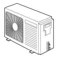
10-4-5. Refrigerant Piping Connection
10-4-4. Refrigerant Piping
For reference
If a heating operation is to be continuously performed for a long time
under the condition that the outdoor temperature is 0°C or lower, draining
defrosted water may be difÞ cult due to the bottom plate freezing, resulting in
trouble with the cabinet or fan.
It is recommended to procure an anti-freeze heater locally in order to safely
install the air conditioner.
For details, contact the dealer.
Flaring
1. Cut the pipe with a pipe cutter.
Knockout of pipe cover
Knockout procedure
Obliquity Roughness Warp
Pipe
Die
• The indoor/outdoor connecting pipes can be connected in 4 directions.
Take off the knockout part of the pipe cover through which pipes or wires
will pass through the base plate.
• Detach the pipe cover and tap on the knockout section a few times with
the shank of a screwdriver. A knockout hole can easily be punched.
• After punching out the knockout hole, remove burrs from the hole and
then install the supplied protective bush and guard material around the
passage hole to protect wires and pipes.
Be sure to attach the pipe covers after pipes have been connected. Cut
the slits under the pipe covers to facilitate the installation.
After connecting the pipes, be sure to mount the pipe cover. The pipe
cover is easily mounted by cutting off the slit at the lower part of the pipe
cover.
* Be sure to wear heavy work gloves while working.
Rear direction
Pipe cover
Side direction
Front direction
Drain nipple
Waterproof rubber cap
(5pcs.)
Drain nipple
Waterproof rubber cap
Down direction
Supplied protective bush
Supplied passage hole guard material
* Attach the guard material securely
so that it does not come loose.
A
FILE NO. SVM-13004
– 64–

 Loading...