Do you have a question about the Toshiba RAS-M07N3KV2-E and is the answer not in the manual?
Power supply cord requirements for outdoor appliance use.
Precautions for R410A refrigerant and installation.
Critical safety warnings for installation and electrical work.
Technical data for unit capacities, power, and dimensions.
Information on connection types, wiring, and included items.
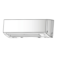
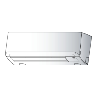
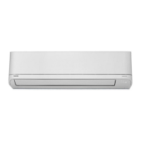
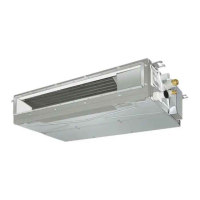
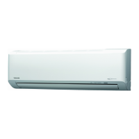
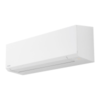
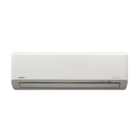
Diagrams illustrating the physical dimensions and mounting of the indoor unit.
Diagrams showing dimensions for remote controller holders.
Overview of control logic between indoor and outdoor units.
Detailed explanation of various operational modes and functions.
How the auto restart feature works and how to set it.
Explanation of remote controller parts and their functions.
Covers basic operation, mode selection, and fan control.
Explains ECO, Temporary, Self-Cleaning, and other modes.
Details on using the remote for various functions.
Describes how the system receives and processes operation commands.
Explains mode selection for 2-room operation.
Details how cooling and heating operations are controlled.
How the unit automatically selects cooling or heating mode.
Explanation of the dehumidification mode and fan speed control.
Details fan speed settings for cooling and AUTO modes.
Fan speed control details for heating operation.
How compressor speed adjusts capacity based on temperature.
Controls to protect against extreme heat exchanger temperatures.
How louvers control air direction and swing.
Details on the energy-saving ECO mode for cooling and heating.
How to perform temporary AUTO or COOL operation.
Purpose and operation of the self-cleaning feature.
Flowchart for setting or canceling self-cleaning.
How to set remote control for multiple units.
Operation of the quiet mode for reduced fan noise.
Functionality of the comfort sleep mode for energy saving.
Purpose and setting of the short timer.
Fully automated operation for preferred conditions.
Operation for faster cooling/heating and increased fan speed.
How the filter indicator works and how to reset it.
How to set or cancel the auto restart function.
Explains operation of ONE-TOUCH, AUTO, and COOL/HEAT modes.
Details on dehumidification mode and temperature settings.
How to start/stop Hi-POWER mode for faster cooling.
How to start/stop ECO mode for energy saving.
Procedure for temporary operation without remote control.
Setting ON/OFF timers and daily timers.
Setting and operating preferred user settings for future use.
How to set or cancel auto restart after power failure.
How to operate in quiet mode for reduced fan noise.
How comfort sleep mode saves energy and turns off automatically.
How to cancel the auto restart function.
Step-by-step guide to setting the auto restart function.
How timer settings are affected by power failure.
Lists and describes remote controller buttons and indicators.
Explains how to use ONE-TOUCH, AUTO, and COOL/HEAT modes.
Details on dehumidification mode and temperature settings.
How to start/stop Hi-POWER mode for faster cooling.
How to start/stop ECO mode for energy saving.
Procedure for temporary operation without remote control.
Setting ON/OFF timers and daily timers.
Setting and operating preferred user settings for future use.
How to set or cancel auto restart after power failure.
How to operate in quiet mode for reduced fan noise.
How comfort sleep mode saves energy and turns off automatically.
Setting and operating preferred user settings for future use.
How to set or cancel auto restart after power failure.
How to operate in quiet mode for reduced fan noise.
How comfort sleep mode saves energy and turns off automatically.
Explains all indications on the remote controller display.
Visual guide for installing indoor and outdoor units.
Instructions for installing batteries in the wireless remote controller.
Information on optional parts and outdoor unit mounting.
Lists all included accessories and installation components.
Lists new tools required for R410A and changes from R22 models.
Details on selecting the installation place for the indoor unit.
Procedures for cutting wall holes and mounting the installation plate.
Guidelines for choosing an optimal remote control reception location.
Steps for connecting the power supply and control cables.
Instructions for wired remote control connection.
Procedures for piping and drain hose setup.
Steps for attaching the air inlet grille.
Instructions for shaping pipes and drain hoses.
Procedure for securing the drain cap.
Details on piping connection for left-side installations.
Steps for securely attaching the indoor unit to the installation plate.
Instructions for ensuring proper drain hose slope and connection.
Covers remote control A-B selection and test operation.
How to set the auto restart function.
Introduction to troubleshooting procedures and inverter precautions.
Safety warnings for handling high-voltage components.
Initial checks for power supply, voltage, and normal operations.
Identifies normal program operations that might be mistaken for faults.
Methods for initial troubleshooting diagnosis.
Interpreting LED indicators for self-diagnosis codes.
How to use the remote in service mode for self-diagnosis.
Step-by-step guide to accessing and using service mode.
Important precautions to follow after servicing.
Detailed check codes for diagnosis and actions.
More check codes for diagnosis and actions.
Troubleshooting based on observed symptoms.
Initial checks for power issues and basic components.
Troubleshooting steps if power remains off after PC board replacement.
Troubleshooting steps for a non-operating indoor fan motor.
Steps to inspect the AC fan motor windings and voltage.
Flowchart for diagnosing remote control issues.
Diagnosing issues related to interconnecting and serial signal wires.
Checks for voltage and transmission to diagnose outdoor unit issues.
Troubleshooting steps when the outdoor unit stops after operation.
Procedure for checking pulse motor valve and sensors.
Flowchart for diagnosing inverter assembly issues.
Steps to check compressor, fan motor, and capacitor.
Procedures for checking the PC Board.
Precautions and procedures for inspecting the indoor PC board.
Detailed checks for power supply, compressor, and fan motor.
Diagram showing the layout of the indoor PC board.
Resistance values for temperature sensors at different temperatures.
Resistance checks for remote control and louver motor.
Resistance checks for compressor, fan motor, valves, and sensors.
Procedures for checking electrolytic capacitors and converter modules.
Steps to test the outdoor fan motor's condition.
General warnings and safety precautions for part replacement.
Procedure for removing and assembling the front panel of the indoor unit.
Steps for removing and assembling the electric parts box.
Procedure to remove and replace the horizontal louver and heat exchanger.
Procedure for removing and installing the bearing base.
Steps for removing and installing the fan motor.
Cautions and steps for reassembling the cross flow fan.
Procedure for replacing the microcomputer.
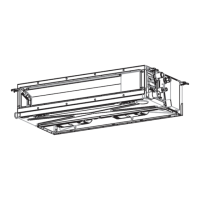
Exploded view and parts list for the indoor unit.
Exploded view and parts list for specific indoor unit components.
| Brand | Toshiba |
|---|---|
| Model | RAS-M07N3KV2-E |
| Category | Air Conditioner |
| Language | English |