EasyManua.ls Logo

Toshiba RAS-M07SKV-E User Manual

Toshiba RAS-M07SKV-E
85 pages
To Next Page IconTo Next Page
Page #1 background imageLoading...
Page #1 background image
R410A
FILE NO. SVM-07034-2
SERVICE MANUAL
SPLIT TYPE
Indoor Unit
<High Wall, Heat Pump Type>
RAS-M07SKV-E
Revised May, 2009
<High Wall, Cooling Type>
RAS-M10SKCV-E
RAS-M13SKCV-E
RAS-M16SKCV-E
RAS-M10SKV-E
RAS-M13SKV-E
RAS-M16SKV-E
Question and Answer IconNeed help?

Do you have a question about the Toshiba RAS-M07SKV-E and is the answer not in the manual?

Toshiba RAS-M07SKV-E Specifications

General IconGeneral
Cooling Capacity2.0 kW
Heating Capacity2.5 kW
Power Supply220-240 V, 50 Hz
RefrigerantR410A
Weight (Indoor Unit)8 kg
Outdoor Unit Noise Level48 dB
Noise Level (Outdoor)48 dB

Summary

TOSHIBA SERVICE MANUAL AIR-CONDITIONER SPLIT TYPE

Indoor Unit Models

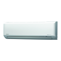
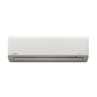
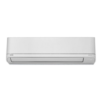
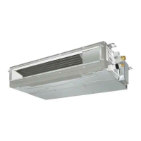
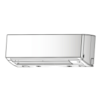
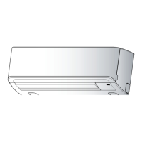
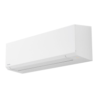
Lists the specific indoor unit models covered by this service manual.

SAFETY PRECAUTIONS

DANGER

Details critical safety warnings and potential hazards during operation and maintenance.

Specifications

2-2-1. Heatpump type

Specifies combinations available for heat pump type indoor units with outdoor units.

REFRIGERANT R410A

3-1. Safety During Installation/Servicing

Crucial safety guidelines for handling R410A refrigerant during installation and servicing.

Tools

3-3-1. Required Tools

Lists essential tools required for R410A air conditioner installation and servicing.

Recharging of Refrigerant

CONSTRUCTION VIEWS

WIRING DIAGRAM

5-1. Model Specifications for Wiring

Wiring diagrams and specifications for specific indoor unit models.

SPECIFICATIONS OF ELECTRICAL PARTS

REFRIGERANT CYCLE DIAGRAM

CONTROL BLOCK DIAGRAM

8-1. Indoor Unit Control

Diagram illustrating the control logic and components of the indoor unit.

OPERATION DESCRIPTION

9-1. Outline of Air Conditioner Control

Overview of the air conditioner's control system and its main functions.

Basic Operation

2. Indoor fan motor control

Details on how the indoor fan motor speed is controlled under various conditions.

AUTO operation

DRY operation

Description of the DRY operation mode and its temperature control.

Release protective control by temperature of indoor heat exchanger

ECO operation

Self-Cleaning function

QUIET mode

COMFORT SLEEP

Description of the COMFORT SLEEP mode for enhanced user comfort.

One-Touch Comfort

Hi-POWER Mode

Details on the Hi-POWER mode for rapid cooling or heating.

Auto Restart Function

9-3-1. How to Set the Auto Restart Function

Step-by-step guide on how to enable the auto restart feature.

Remote control

9-4-1. Remote control and its functions

Overview of the remote control's buttons and their basic functions.

Indications on Remote Controller

INSTALLATION PROCEDURE

10-1. Installation Diagram of Indoor and Outdoor Units

Visual guide showing the layout for installing indoor and outdoor units.

Installation/Servicing Tools

Indoor Unit Installation

10-3-1. Installation Place

Guidelines for selecting an appropriate installation location for the indoor unit.

Electrical Work

Wiring Connection

Piping and Drain Hose Installation

Indoor Unit Installation

HOW TO DIAGNOSE THE TROUBLE

11-1. First Confirmation

Initial checks to perform before detailed troubleshooting.

Judgment by Flashing LED of Indoor Unit

Self-Diagnosis by Remote Controller (Check Code)

11-4-1. How to Use Remote Controller in Service Mode

Procedure for entering service mode to perform remote controller diagnostics.

Judgment of Trouble by Every Symptom

11-5-1. Indoor Unit (Including Remote Controller)

Troubleshooting guide for issues related to the indoor unit and remote controller.

Indoor fan motor does not operate

Troubleshooting for remote controller

Wiring Failure (Interconnecting and Serial Signal Wire)

(1) Outdoor unit does not operate

Troubleshooting specific wiring failures causing outdoor unit non-operation.

How to Check Simply the Main Parts

11-9-1. How to Check the P.C. Board (Indoor Unit)

Procedure for inspecting the indoor unit's P.C. board for defects.

HOW TO REPLACE THE MAIN PARTS

12-1. Indoor Unit

Detailed steps for disassembling and reassembling the indoor unit.

Microcomputer

EXPLODED VIEWS AND PARTS LIST

13-1. Indoor Unit (1)

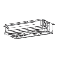
Exploded view and parts list for the indoor unit components.

Indoor Unit (2)

Related product manuals