EasyManua.ls Logo

Toshiba RAS-M10SKCV-E User Manual

Toshiba RAS-M10SKCV-E
85 pages
To Next Page IconTo Next Page
Page #1 background imageLoading...
Page #1 background image
R410A
FILE NO. SVM-07034
SERVICE MANUAL
SPLIT TYPE
Indoor Unit
<High Wall, Heat PumpType>
RAS-M10SKV-E
RAS-M13SKV-E
RAS-M16SKV-E
July, 2007
<High Wall, Cooling Type>
RAS-M10SKCV-E
RAS-M13SKCV-E
RAS-M16SKCV-E
Question and Answer IconNeed help?

Do you have a question about the Toshiba RAS-M10SKCV-E and is the answer not in the manual?

Toshiba RAS-M10SKCV-E Specifications

General IconGeneral
BrandToshiba
ModelRAS-M10SKCV-E
CategoryAir Conditioner
LanguageEnglish

Summary

1. SAFETY PRECAUTIONS

R410A Refrigerant Installation Safety

Precautions for R410A refrigerant installation to avoid impurities.

Power Disconnection Safety

Requirement for circuit breaker/switch for disconnection.

High Voltage Warning

Warning about high voltage circuits and touching P.C. boards.

1. SAFETY PRECAUTIONS (Continued)

General Installation & Servicing Warnings

Covers safety guards, weight, leaks, electrician, wiring, grounding.

Installation Environmental Precautions

Covers water exposure, vibration, sharp edges, earthquakes.

2. Specifications

Outdoor Unit Combinations

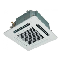
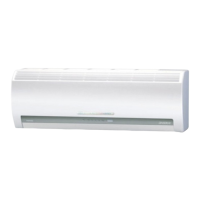
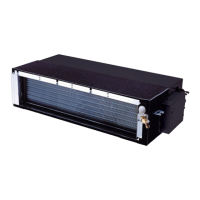
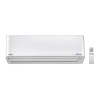
Lists outdoor units compatible with indoor units.

2-2. Specifications

Indoor Unit Specs

Details specifications for indoor units like dimensions, weight, noise.

Outdoor Unit Specs

Details specifications for outdoor units like dimensions, weight, motor output.

2-2. Specifications (Continued)

Wiring Details

Details power supply and interconnection wiring.

Included Accessories

Lists included accessories.

3. R410A Refrigerant Information

R410A Handling Safety

Safety precautions when handling R410A refrigerant.

Refrigerant Piping Requirements

Specifies piping materials and installation.

3-2. Refrigerant Piping Requirements (Continued)

Piping Material Specifications

Details copper pipe specifications and joints.

Piping Material Processing

Procedures for cutting, deburring, and flaring pipes.

3-2-2. Processing of Piping Materials (Continued)

Flare Processing Procedures

Procedures and dimensions for flare processing.

Flare Dimensions

Tables for flare and flare nut dimensions for R410A and R22.

3-2. Flare Connecting Procedures and Precautions

Flare Connection Safety

Steps and precautions for connecting flares, including torque.

3-3. Tools

R410A Required Tools

Lists exclusive and general tools for R410A installation.

3-4. Refrigerant Recharging Procedure

3-5. Pipe Brazing Procedures

Brazing Filler Materials

Types of brazing filler materials.

Brazing Flux Information

Reason for flux use and its characteristics.

3-5. Pipe Brazing Procedures (Continued)

Brazing Oxidation Prevention

Procedures for brazing, including preventing oxidation.

Brazing Material Compatibility

Table showing compatible brazing materials.

4. Indoor Unit Construction Views

5. Indoor/Outdoor Unit Wiring Diagram

6. Electrical Parts Specifications

7. Refrigerant Cycle Flow Diagram

8. System Control Block Diagram

Indoor Unit Control System

Block diagram of the indoor unit's control system and functions.

9. OPERATION DESCRIPTION

Air Conditioner Control Overview

Overview of the air conditioner's control system and roles.

9-2. Operation Description

Basic Operation Control

Covers general operation control and modes.

2-Room Operation Mode Selection

How modes are selected in multi-room operation.

Cooling and Heating Operation

How cooling and heating operations are controlled.

9-2. Operation Description (Continued)

Automatic Operation Mode

Automatic mode selection based on room temperature.

Dry Mode Operation

Dehumidification mode operation.

9-2. Operation Description (Continued)

Indoor Fan Speed Control

Fan speed control in cooling and heating modes.

9-2. Operation Description (Continued)

Capacity Adjustment Control

Adjustment of cooling/heating capacity via compressor revolution.

9-2. Operation Description (Continued)

Heat Exchanger Temperature Protection

Protection control based on indoor heat exchanger temperature.

9-2. Operation Description (Continued)

Airflow Direction Control

Control of air direction via louvers.

9-2. Operation Description (Continued)

Energy Saving (ECO) Operation

Energy-saving operation mode.

9-2. Operation Description (Continued)

Temporary Operation Mode

How to perform temporary AUTO or COOL operation.

9-2. Operation Description (Continued)

Indoor Unit Self-Cleaning

Function to clean the indoor unit and prevent mold.

9-2. Operation Description (Continued)

Self-Cleaning Function Management

How to cancel or set the Self-Cleaning function.

9-2. Operation Description (Continued)

Remote Control Unit Selection

Setting remote control for single unit operation.

9-2. Operation Description (Continued)

Quiet Operation Mode

Operation for reduced noise level.

Comfort Sleep Mode

Sleep mode for energy saving and comfort.

Short Timer Function

Timer function for testing or trial operation.

9-2. Operation Description (Continued)

One-Touch Comfort Feature

Automated operation for preferred regional conditions.

Hi-POWER Operation Mode

Mode for faster cooling or heating.

Filter Maintenance Indicator

Indicator for filter cleaning and how to turn it off.

9-3. Automatic Restart Function

Setting Auto Restart

Procedure to enable the auto restart function.

9-3. Automatic Restart Function (Continued)

Canceling Auto Restart

Procedure to disable the auto restart function.

Timer Operation on Power Failure

How timer operation is affected by power failure.

9-4. Remote Controller Usage

Remote Control Functions

Identification of remote control buttons and their purposes.

Remote Control Operation Modes

How to use various remote control modes like ONE-TOUCH, AUTO, COOL/HEAT.

9-4. Remote Controller Usage (Continued)

Dry Mode Operation Details

Instructions for Dry mode operation.

Hi-POWER Operation Details

How to activate Hi-POWER mode.

ECO Operation Details

How to activate ECO energy-saving mode.

Timer Operation Settings

Setting ON and OFF timers, and Everyday Timer.

9-4. Remote Controller Usage (Continued)

Preset Operation Settings

Setting and operating preset preferences.

Auto Restart Function Setup

Setting and canceling the auto restart function.

Quiet Operation Details

How to operate in quiet mode.

Comfort Sleep Operation Details

Sleep mode for energy saving and comfort.

9-4. Remote Controller Usage (Continued)

Remote Controller Indications Explanation

Explains indicators and symbols on the remote display.

9-5. Intermittent Fan Control (Heating)

10. Installation Procedure

Unit Installation Diagram

Visual guide for indoor and outdoor unit placement and piping.

10-2. Installation Parts and Accessories

10-2-3. R410A Installation Tools

10-3. Indoor Unit Installation Steps

Indoor Unit Placement Guidelines

Criteria for selecting the indoor unit installation location.

Drilling and Plate Mounting

Steps for drilling holes and mounting the installation plate.

10-3. Indoor Unit Installation Steps (Continued)

Secure Mounting Plate Installation

Procedures for securely mounting the installation plate on the wall.

Electrical Connection Requirements

Requirements for connecting the power supply.

Connecting Cable Installation

How to connect the connecting cable to the indoor unit.

10-3-5. Piping and Drain Hose Setup

Front Panel Slit Cutting

Cutting slots in the front panel for piping.

Drain Hose Relocation

Relocating the drain hose and cap.

10-3. Indoor Unit Installation Steps (Continued)

Drain Cap Attachment

Procedure for attaching the drain cap.

Left-Side Piping Connection

Connecting pipes from the left side, including bending radius.

Right/Left Piping Panel Slits

Cutting front panel slits for right/left piping.

10-3-7. Drainage System Installation

Hanging and Securing Indoor Unit

Steps for hanging and securing the indoor unit on the installation plate.

11. Troubleshooting Guide

Initial Troubleshooting Checks

Initial checks for power supply and voltage.

11-2. Trouble Diagnosis Methods

LED Flashing Code Diagnosis

Interpreting LED flashing codes for self-diagnosis.

11-4. Remote Controller Self-Diagnosis

Service Mode Remote Controller Usage

Steps to enter service mode and read error codes.

11-4-2. Servicing Precautions

11-5. Troubleshooting by Symptom

Indoor Unit & Remote Controller Issues

Diagnosing issues with the indoor unit and remote controller.

11-5-1. Indoor Unit (Continued)

Indoor Fan Motor Not Operating

Troubleshooting steps for a non-operating indoor fan motor.

11-5-1. Indoor Unit (Continued)

Fan Motor Auto-Rotation Diagnosis

Diagnosing fan motor auto-rotation issue.

11-5-3. Remote Controller Troubleshooting

11-5-2. Wiring and Signal Failure Diagnosis

Outdoor Unit Operation Failure

Troubleshooting when the outdoor unit is not operating.

Outdoor Unit Intermittent Stop

Diagnosing why the outdoor unit stops after starting.

11-9. Simple Main Part Checks

Indoor Unit PC Board Inspection

Procedures for inspecting the indoor unit's P.C. board.

11-9-2. Indoor Unit PC Board Layout

11-9-3. Indoor Unit Component Checks

12. Main Parts Replacement Guide

Indoor Unit Parts Replacement

Steps for disassembling and replacing indoor unit parts.

12-1. Indoor Unit Parts Replacement (Continued)

Front Panel Removal and Reassembly

Procedure for removing and reassembling the front panel.

12-1. Indoor Unit Parts Replacement (Continued)

Electric Parts Box Replacement

Procedure for removing and assembling the electric parts box.

12-1. Indoor Unit Parts Replacement (Continued)

Horizontal Louver Removal

Procedure for removing the horizontal louver.

Heat Exchanger Removal

Procedure for removing the heat exchanger.

12-1. Indoor Unit Parts Replacement (Continued)

Bearing Replacement Procedure

Procedure for removing and replacing the bearing.

12-1. Indoor Unit Parts Replacement (Continued)

Fan Motor Removal Procedure

Procedure for removing the fan motor.

12-1. Indoor Unit Parts Replacement (Continued)

Cross Flow Fan Reassembly Caution

Caution and procedure for reassembling the cross flow fan.

12-2. Microcomputer and PC Board Replacement

13. Exploded Views and Parts List

Indoor Unit Parts List (1)

Exploded view and part list for the indoor unit.

13. Exploded Views and Parts List (Continued)

Indoor Unit Parts List (2)

Exploded view and part list for the indoor unit.

Related product manuals