– 58 –
10-7. Refrigerant piping
CAUTION
When the refrigerant pipe is long, provide
support brackets at intervals of 2.5 to 3 m to
clamp the refrigerant pipe. Otherwise,
abnormal sound may be generated. Use the
flare nut attached with the indoor unit or
R410A flare nut.
Permissible piping length and height difference
They vary depending on the outdoor unit. For details, refer to the Installation
Manual attached to the outdoor unit.
Pipe size
Connecting refrigerant piping
Flaring
1. Cut the pipe by a pipe cutter.
Remove burrs completely. (Remaining burrs may cause gas leakage.)
2. Insert a flare nut into the pipe, and flare the pipe. Use the flare nut provided
with the unit or the one used for the R410A refrigerant. The flaring
dimensions for R410A are different from the ones used for the conventional
R22 refrigerant. A new flare tool manufactured for use with the R410A
refrigerant is recommended, but the conventional tool can still be used if the
projection margin of the copper pipe is adjusted to be as shown in the
following table.
Projection margin in flaring: B (Unit: mm)
Flaring diameter size: A (Unit: mm)
* In case of flaring for R410A with the conventional flare tool, pull it out approx.
0.5 mm more than that for R22 to adjust to the specified flare size. The
copper pipe gauge is useful for adjusting projection margin size.
• The sealed gas was sealed at the atmospheric pressure so when the flare
nut is removed, there will no “whooshing” sound: This is normal and is not
indicative of trouble.
• Use two wrenches to connect the indoor unit pipe.
• Use the tightening torque levels as listed in the table below.
• Tightening torque of flare pipe connections.
Pressure of R410A is higher than that of R22. (Approx. 1.6 times) Therefore,
using a torque wrench, tighten the flare pipe connecting sections which
connect the indoor and outdoor units of the specified tightening torque.
Incorrect connections may cause not only a gas leak, but also a trouble of
the refrigeration cycle.
CAUTION
Tightening with an excessive torque may
crack the nut depending on installation
conditions.
Airtight test / Air purge, etc.
For air tightness test, vacuum drying and adding refrigerant, refer to the
Installation Manual attached tothe outdoor unit.
Open the valve fully
Open the valve of the outdoor unit fully.
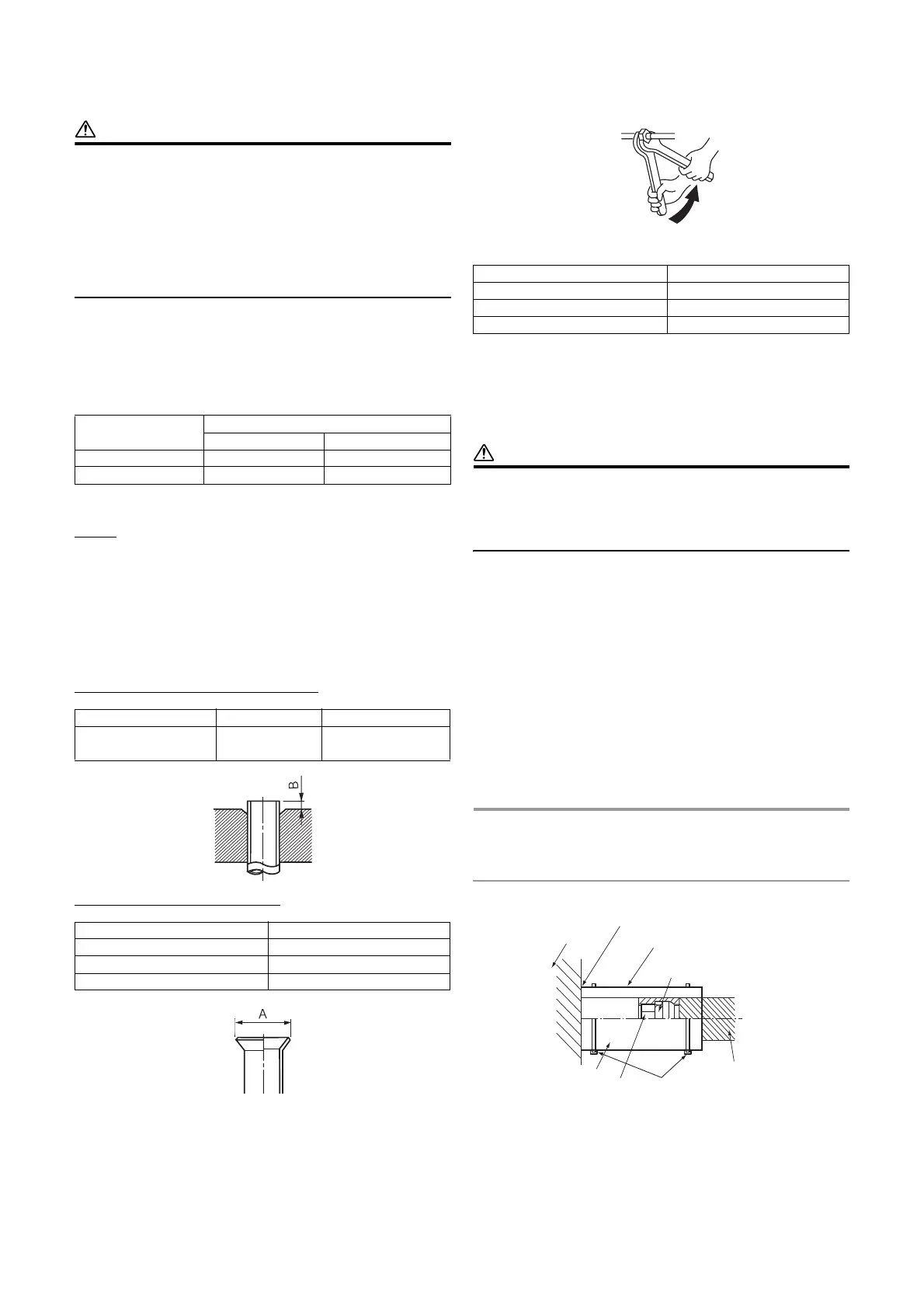
Heat insulation process
Apply heat insulation for the pipes separately at liquid side and gas side.
• For the heat insulation to the pipes at gas side, use the material with heat-
resisting temperature 120 °C or higher.
• To use the attached heat insulation pipe, apply the heat insulation to the pipe
connecting section of the indoor unit securely without gap.
REQUIREMENT
• Apply the heat insulation to the pipe connecting section of the indoor unit
securely up to the root without exposure of the pipe. (The pipe exposed to
the outside causes water leak.)
• Wrap heat insulator with its slits facing up (ceiling side).
Model RAS-
Pipe size (mm)
Gas side Liquid side
M07,10,13G3DV Ø9.5 Ø6.4
M16G3DV Ø12.7 Ø6.4
Outer dia. of copper pipe R410A tool used Conventional tool used
6.4, 9.5
0 to 0.5 1.0 to 1.5
12.7
Outer dia. of copper pipe A
+0
–0.4
6.4 9.1
9.5 13.2
12.7 16.6
Outer dia. of connecting pipe (mm) Tightening torque (N•m)
6.4 14 to 18 (1.4 to 1.8 kgf•m)
9.5 34 to 42 (3.4 to 4.2 kgf•m)
12.7 49 to 61 (4.9 to 6.1 kgf•m)
Work using double spanner
Wrap the pipe with the attached heat insulator
without any gap between the indoor unit.
The seam must be faced
upward (ceiling side).
Indoor unit
Flare nut
Union
Heat insulation
pipe
(Accessory)
Banding band
(Locally
procured)
Heat insulator
of the pipe