– 78 –
No. Part name Procedure Remarks
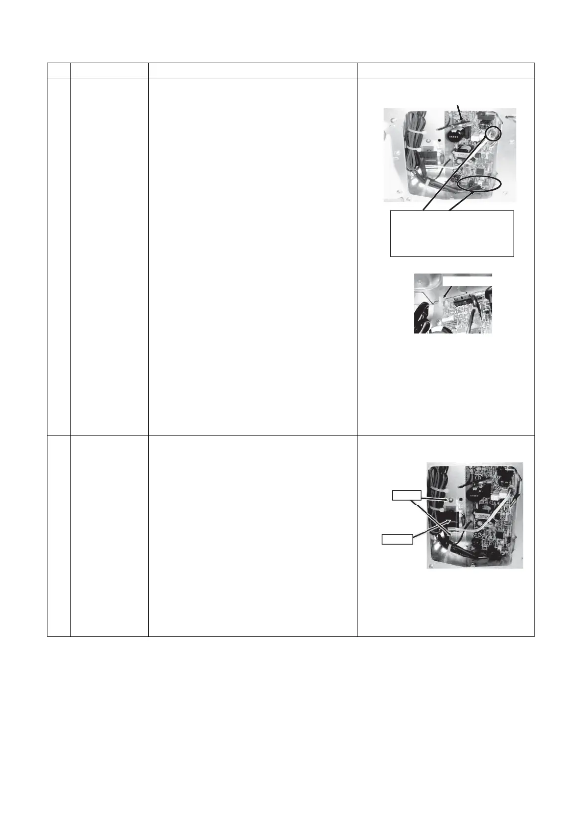
6 Control P.C.
board
1. Detachment
1) Perform the procedure in 1 of “3Electric parts
box cover.”
2) Disconnect the connectors from other
components from the control P.C. board.
NOTE)
Unlock the lock of the housing to disconnect the
connectors.
CN41 … Remote control connector (2P: Blue)
CN67 … Power supply connector (5P: Black)
CN101 … TC sensor (2P: Black)
CN102 … TCJ sensor (2P: Red)
CN104 … TA sensor (2P: Yellow)
CN210 … Fan motor power supply (7P: White)
CN34 … Float switch (3P: Red)
CN504 … Drain pump lead (2P: White)
CN01…Reactor (2P: Blue)
3) Unlock the card edge spacers (4 locations) to
remove the control P.C. board.
2. Attachment
1) Attach the control P.C. board to the clamps.
2) Reconnect the cables that you disconnected in
step 1-2) of “6Control P.C. board.”
NOTE)
Check there is no missing or contact failure on
the connectors.
7 Reactor 1. Detachment
1) Perform the procedure in 1 of “3 Electric
parts box cover.”
2) The connector of reactor (CN01) is removed
from control P.C. board.
3) Remove the screws that fix the reactor.
(Ø4×10 2 pcs)
2. Attachment
1) Attach the reactor to the control P.C. board.
2) Reconnect the detached connector.
NOTE)
Check there is no missing or contact failure on
the connectors.
Electric parts box
If it is difficult to disconnect the bottom
connector, first remove the card edge
spacers (2 locations at bottom), and
then proceed.
Card edge spacer
Screws
Reactor