1-11-10 E3NG1TR
Check the ECO+5V, ECO+9V
line and replace P1(AV
ASSEMBLY) or P3(PW/SW
ASSEMBLY) if defective.
Replace P1(AV
ASSEMBLY).
Ye s N o
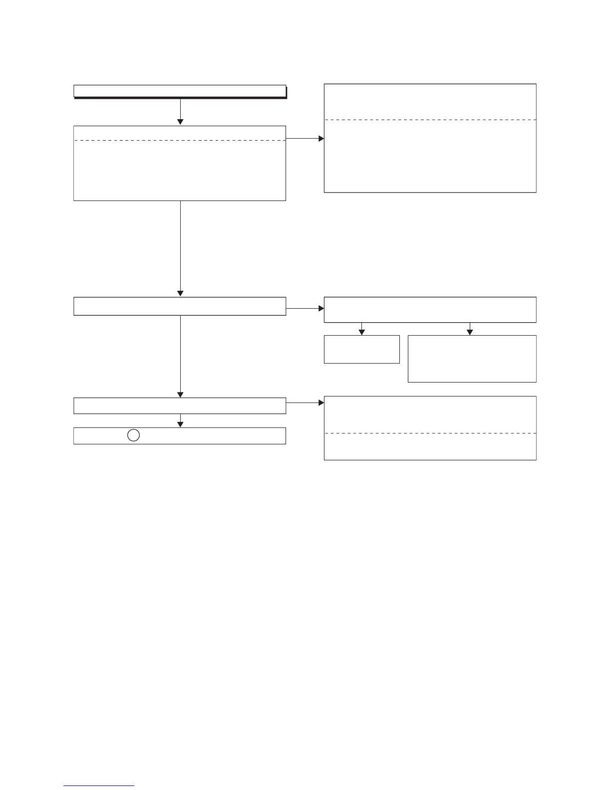
FLOW CHART NO.6
Audio E-E does not appear normally.
Are the audio signals inputted to each pin of IC1509?
Check the line between audio input terminal and
each pin of IC1509, and replace P1(AV ASSEMBLY),
P6(BOARD DTV MODULE UNIT) or TU1800 if defective.
Check the line between each pin of IC1509 and
each pin of CN1502, and replace P1(AV ASSEMBLY),
if defective.
Are the audio signals outputted to Pin(79,80) of IC1509?
Ye s
Are the audio signals outputted to Pin(11,13) of CN1502?
Ye s
Ye s
No
No
No
IC1509 AUDIO-IN1 (AV1)86,87PIN
IC1509 AUDIO-IN (FRONT)91,92PIN
IC1509 AUDIO-IN2 (AV2)89,90PIN
IC1509 TUNER-AUDIO84,85PIN
IC1509 DTV-AUDIO93,94PIN
IC1509
→
JK150486,87PIN
IC1509
→
JK3002,
JK3003
91,92PIN
IC1509
→
JK200189,90PIN
AUDIO-IN1 (AV1)
AUDIO-IN (FRONT)
IC1509
→
CN1502 13PIN
→
CN1502 11PIN
79PIN
IC1509 80PIN
AUDIO(R)-IN
AUDIO(L)-IN
IC1509
→
TU1800 6PIN 84,85PIN
IC1509
→
CN1800 29,30PIN93,94PIN
TUNER-AUDIO
DTV-AUDIO
AUDIO-IN2 (AV2)
Is 5V voltage supplied to Pin(27,29,47,63) of IC1509?
Is 9V voltage supplied to Pin(75) of IC1509?
Continued to B on the next page.
 Loading...