Do you have a question about the Toshiba S15 and is the answer not in the manual?
Check for foreign materials (metal shavings, hardware) in the drive assembly.
Verify input, output, and control wiring integrity and separation.
Inspect motor terminal box for power factor correction capacitors and wire condition.
Verify tightness and condition of the drive to motor ground connection.
Ensure grounding capacitor is DISABLED on specific grounding systems to prevent failure.
Measure and verify line voltage, DC bus voltage, and control voltage.
Set SW1 switch to Sink or Source to avoid keypad display errors.
Verify motor rotates in the correct direction by running at 5 Hz.
Confirm fans operate correctly and air flows in the intended direction.
Verify analog input polarity and that scaling is adjusted as needed.
Verify digital input operation and monitor assigned functions.
Verify digital output operation and monitor assigned functions.
Verify analog output operation and check calibration settings.
Verify basic parameters and record new values for any changed settings.
Record inverter type, serial number, and CPU versions from nameplate and monitor.
The Toshiba S15 Application Note 1.8.0 Startup Guide provides a comprehensive checklist and programming instructions for setting up and configuring the S15 inverter. This guide is designed to assist users in the initial installation, verification, and parameter programming of the device, ensuring proper functionality and safe operation. It is intended for a Level 1 user and is estimated to take 20-30 minutes to complete, assuming the user has already reviewed S15 Application Note 1.1.0, which covers navigating menus and parameters.
The startup process is divided into three main steps: Visual Inspection, Startup Parameters, and Model Information.
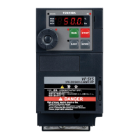
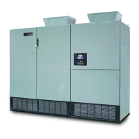
The Toshiba S15 inverter is a device designed to control the speed and torque of electric motors. It offers various input and output options, allowing for flexible integration into different control systems. The device supports both digital and analog inputs and outputs, enabling precise control and monitoring of motor operation. Key functions include motor speed control, direction control, fault status indication, and various protective features.
The S15 inverter offers a range of features for flexible and reliable operation:
Visual Inspection: The initial step involves a thorough visual inspection to ensure the device is free from foreign materials like metal shavings or hardware, which could interfere with its operation. This step also includes verifying the correct wiring of input and output terminals, ensuring control wires are in separate conduits, and confirming that motor leads do not share conduits with other motor leads. Wire tightness and condition (checking for continuity, frayed wires, and pinched insulation) are also critical aspects of this inspection, extending to the motor terminal box and the drive-to-motor ground connection. The absence of power factor correction capacitors in the motor terminal box is also checked.
Voltage Verification: The guide provides a detailed table for measuring various voltage parameters, including line-to-line voltages (L1-L2, L1-L3, L2-L3), line-to-ground voltages (L1-GND, L2-GND, L3-GND), DC Bus voltage (PA/+ – PC/-), and Control Voltage (P24 – CC). This ensures that the input power supply is within the specified range (±10% of drive rating) and that internal voltages are correct.
SW1 Switch Configuration: The SW1 switch, which determines whether the device operates in Sink or Source mode, must be correctly set. Incorrect configuration will result in a "P-A" error blinking on the keypad, indicating a setup issue.
Motor Rotation Check: To ensure the motor rotates in the correct direction, the guide instructs users to run the drive at 5 Hz using the keypad (default setting). If the rotation is incorrect, users are advised to swap two of the output leads (T1, T2, or T3) and retest.
Blower/Cooling Fan(s) Check: Proper cooling is essential for the inverter's longevity. This step verifies that the cooling fans are operational and that air flows in the correct direction (bottom to top).
Analog Inputs: The S15 supports various analog input types, including VIC (4-20mA), VIA (0-10VDC), and VIB (-10 to +10VDC). Users need to verify the polarity of these inputs, and scaling can be adjusted using parameters F201 to F221 for precise control.
Digital Inputs: The S15 features seven digital inputs, with four capable of having multiple functions assigned. These inputs can be monitored via the keypad in Monitor Mode. The guide provides tables for configuring functions like Forward Run (Terminal F), Reverse Run (Terminal R), Reset (Terminal RES), and various Preset Speeds (Terminals S1, S2, S3, VIB/S4). Parameters F111 through F117 are used to assign specific functions to these terminals, such as Preset Speed Bit 4, Reverse Run, Reset, and Preset Speed Bits 1 through 4.
Digital Outputs: The S15 has three outputs: two relay outputs and one digital output. Two of these outputs can have multiple functions. Parameter F139 determines if both functions must be true to change state or if only one is required. The guide includes tables for configuring output functions such as Fault Status (Terminals FLA/FLB/FLC), Run Status (Terminals RY/RC), and Speed Reach (Terminals OUT/NO). Parameters F130, F131, F132, F137, and F138 are used to assign functions like Fault Status, Low-Speed Detection Signal, and Speed Reach.
Analog Outputs: For analog output calibration, users are directed to S15 App Note 1.4.0. The guide includes a table for verifying analog output operation, specifically for the FM terminal, which defaults to Output Frequency (FASL parameter).
Startup Parameters (Programming): This section details the programming of basic parameters. It recommends a Carrier Frequency of 4.0kHz and advises changing parameter F701 before adjusting the V/Hz control mode to avoid dealing with percentages. Motor kW and RPM are not strictly necessary unless performing an auto-tune. Key parameters to configure include Overload Characteristic Selection (AUL), Command Mode Selection (FOOD), Frequency Setting Mode Selection 1 (FOOD), Acceleration Time 1 (ACC), Deceleration Time 1 (DEC), Maximum Frequency (FH), Upper Limit Frequency (UL), Lower Limit Frequency (LL), Base Frequency 1 (UL), Base Frequency Voltage 1 (PE), V/Hz Control Mode Selection (PE), Current/Voltage Display Unit Selection (F701), Motor Electronic Thermal Protection (EHC), PWM Carrier Frequency (F300), Auto-Restart Control Selection (F301), Retry Selection (F303), and Easy Key Function Selection (F750). The guide provides default values and space to record new values for these parameters.
While the document primarily focuses on initial setup, several aspects contribute to the device's long-term reliability and ease of maintenance:
Detailed Checklists: The comprehensive checklists for visual inspection, wiring, and voltage verification help prevent common installation errors that could lead to device malfunction or premature failure. By ensuring proper wiring and connections from the outset, the likelihood of future issues is significantly reduced.
Monitoring Capabilities: The ability to monitor digital inputs and output states via the keypad in Monitor Mode allows for quick diagnostics and troubleshooting if operational issues arise. This feature helps identify the source of problems without requiring extensive disassembly or specialized tools.
Parameter Adjustments: The guide details various adjustable parameters that allow for fine-tuning the inverter's performance to match specific application requirements. This flexibility ensures optimal operation and can help extend the life of both the inverter and the connected motor by preventing overloads or inefficient operation.
Error Indicators: The "P-A" blinking error for incorrect SW1 switch setting is an example of an immediate feedback mechanism that aids in troubleshooting during setup.
Motor Overload Protection: The "Motor Electronic Thermal Protection" parameter (EHC) is crucial for protecting the motor from damage due to excessive current, thereby extending its lifespan and reducing maintenance needs.
Auto-Restart and Retry Functions: Parameters like "Auto-Restart Control Selection" (F301) and "Retry Selection" (F303) allow the inverter to attempt recovery from certain non-critical faults, potentially reducing downtime and the need for manual intervention.
Model Information Recording: The final step involves recording model information from the nameplate and CPU versions. This information is vital for future reference, such as ordering spare parts, contacting technical support, or performing firmware updates, ensuring that maintenance activities are accurately performed.
In summary, the Toshiba S15 Startup Guide is an essential resource for ensuring the correct and efficient installation and initial configuration of the S15 inverter. Its detailed, step-by-step approach, coupled with comprehensive parameter explanations, contributes significantly to the device's reliable operation and ease of maintenance throughout its service life.
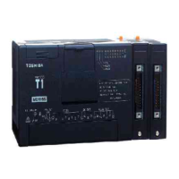
| Type | Programmable Logic Controller |
|---|---|
| Output Voltage | 24V DC |
| Number of Inputs | 16 |
| Number of Outputs | 16 |
| Communication Ports | RS-232, RS-485 |
| Weight | 0.5 kg |
| Operating Temperature | 0°C to 55°C |



 Loading...