EasyManua.ls Logo

Toshiba V200 Series User Manual

Toshiba V200 Series
140 pages
To Next Page IconTo Next Page
Page #1 background imageLoading...
Page #1 background image
UM-V200-E001
Programmable Logic Controllers
USER’S MANUAL
Setup & Operation
CONTENTS
V200 Series PLC
Toshiba International Corporation

Table of Contents

Questions and Answers:

Toshiba V200 Series Specifications

General IconGeneral
ManufacturerToshiba
Power Supply24 VDC
Product SeriesV200
CategoryController
CPU Type32-bit RISC
I/O CapacityUp to 256 points
Communication PortsRS-232, RS-485
Programming SoftwareToshiba PLC Programming Software
Humidity5% to 95% RH (non-condensing)
CertificationsCE, UL

Summary

Manual's Purpose and Scope

Important Notice

Contacting Toshiba’s Customer Support Center

Manual Revisions

General Safety Instructions & Information

Warning Labels Within Manual

Explains signal words (DANGER, WARNING, CAUTION) and their symbols.

Equipment Warning Labels

Examples of warning labels found on the equipment itself.

Preparation

Information on qualified personnel and equipment inspection before installation.

Installation Precautions

Guidelines for location, ambient conditions, and mounting requirements.

Connection, Protection & Setup

Safety measures for personnel and system setup requirements.

System Integration Precautions

Guidelines for using the V200 in industrial control systems safely.

3rd Party Safety Certifications

Details on CE marking, UL certification, and RoHS compliance.

Introduction

Purpose of this Manual

Outlines the manual's objective and scope for V200 PLC users.

V200 Basics

Provides an overview of the V200's versatility and supported functions.

Programming Computer

Lists the minimum system requirements for the programming software.

V200 Features

Details various hardware and software features of the V200 series.

V200 Overview

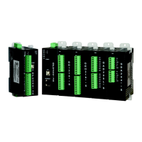
Describes the V200 series controllers as compact, expandable block-style PLCs.

V200 Series Specifications

Lists technical specifications for basic and expansion models of the V200.

Hardware

Unpacking the Unit

Instructions and precautions for carefully unpacking the V200 PLC.

Managing Electrostatic Discharge

Recommendations to minimize damage from electrostatic discharge during handling.

CE Compliance

Information about the V200's conformance to European CE requirements.

Environmental Consideration

Guidelines for operating temperature, humidity, and vibration for the V200.

Safety Precautions

General safety information and hazard classifications for V200 handling.

Installation Instructions

Steps and considerations for mounting the V200 PLC on a DIN rail plate.

Wiring Diagram

Provides diagrams for power and communication wiring connections.

Communications Ports

Details the types and functions of V200 communication ports (COM1, COM2, USB, Ethernet).

Communication Cables

Information on programming cables and their pinouts for PC connection.

Before You Begin

Installing OIL-DS Configuration Software

Step-by-step guide for installing the OIL-DS software on a computer.

Starting OIL-DS Configuration Software

Instructions on how to launch and start the OIL-DS configuration software.

Uninstalling OIL-DS Configuration Software

Procedure for removing the OIL-DS configuration software from the system.

Launching Ladder Editor

Steps to open and use the Ladder Editor within the OIL-DS software.

Creating Sample Ladder Application

Guide on creating a basic ladder logic program using the editor.

Configuration

Configuring V200 with OIL-DS

Detailed process for configuring the V200 CPU using the OIL-DS software.

Tag Database

Explains how to define and manage tags (registers, coils) in the application.

Register Memory Allocation

Details the memory allocation for XW, YW, and MW registers for different models.

Special Input and Output Options

Special I/O Function Overview

Introduces various special I/O functions supported by the V200 PLC.

Single Phase Counter

Configuration details for single-phase counting functions.

Single Phase Speed-Counter

Configuration details for single-phase speed counting functions.

Quadrature Bi-pulse Counter

Configuration details for quadrature bi-pulse counting functions.

Interrupt Input Function

Explains how interrupt inputs activate specific I/O programs.

Pulse Output Function

Details for configuring pulse output functions for Y0 and Y1.

PWM Output Function

Configuration details for Pulse Width Modulation (PWM) output functions.

Operating Systems Overview

System Operating Modes

Describes the V200's operation modes: RUN, HALT, ERROR, HOLD, RUN-F.

Mode Selection

Explains how to switch between operating modes using switches and software.

Programming Information

Devices and Registers

Overview of internal and external PLC registers and their addressing schemes.

Memory Allocation of XW, YW and MW

Table showing memory allocation for registers based on model and slot.

Index Modification

Explains direct and indirect addressing methods using index registers.

Real-time Clock/Calendar

Details on how the V200's real-time clock/calendar functions and data storage.

User Program

Explains the structure of user programs, including main, sub-programs, and subroutines.

Programming Language

Describes the V200's programming language as 'ladder diagram' using relay symbols.

Program Execution Sequence

Explains the sequence of instruction execution within a program rung and block.

Troubleshooting

Troubleshooting Procedure

General steps and safety precautions for troubleshooting PLC issues.

Self Diagnostics

Details on PLC self-diagnosis, error modes, and event history.

Maintenance and Checks

Precautions During Operation

Safety warnings regarding handling the V200 while it is powered on.

Daily Checks

Daily inspection items and corrective measures for system maintenance.

Periodic Checks

Six-month checks for power supply, installation, I/O, and environment.

Maintenance Parts

Recommended spare parts for quick recovery from trouble.

Related product manuals