T2150 Series
Procedure 4 Connector Check
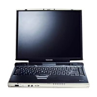
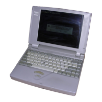
The Display unit has an LCD module, FL, Display switch, and FL inverter board. The FL
and FL inverter board are connected by two cables. The LCD module and system board are
connected by two signal (T2150CDT) cables as shown below. Any of these cables may be
disconnected.
Disassemble the display unit and check the following cable connections. Refer to chapter 4,
Replacement Procedures, for more information about how to disassemble the computer.
Figure 2-3 T2150CDS display connection
 Loading...