10 Information and Control Network TC-net 100 Optical Shared Hub Unit UTNH23A/B User’s Manual
Chapter 3 Setting
3
3.1 Switch Setting
Set the mode and station address switches before switching on the optical shared hub
unit UTNH23A for line A transmission line. These switches are located on the front panel
of the UTNH23A. The switch setting procedures are as follows:
3.1.1 Station address setting switches (STN-H, STN-L)
The UTNH23A has hexadecimal rotary switches to set station addresses, which
determine IP addresses in the TC-net 100 network. Set station addresses (1 to 254)
allocated in building your system in hexadecimal code. Assign an address unique to
each of all nodes in the system. (Refer to
Appendix D Decimal - Hexadecimal
Conversion Tables.)
Use a small screwdriver for setting them.
Note: (h) means hexadecimal.
Figure 3-1 Station Address Setting
3.1.2 Operation mode setting switches (MODE, MODE2)
The UTNH21A has 8-bit DIP switches (MODE) and 4-bit DIP switches (MODE2) used to
select an operation mode. Use a small screwdriver for setting these switches.
Each of these switches is described in Table 3-2 Operation Mode Setting Table..
Figure 3-2
Table 3-1 Station Address Setting
Name Location Setting
Station address H
L
Setting range: 01 to FE (h)
H (Upper digits of address): 0 to F (h)
L (Lower digits of address): 0 to F (h)
STN-H STN-L
Set a station address in hexadecimals. The address
28 corresponds to 1C in hexadecimals (h).
So, turn STN-H to 1 and STN-L to C.
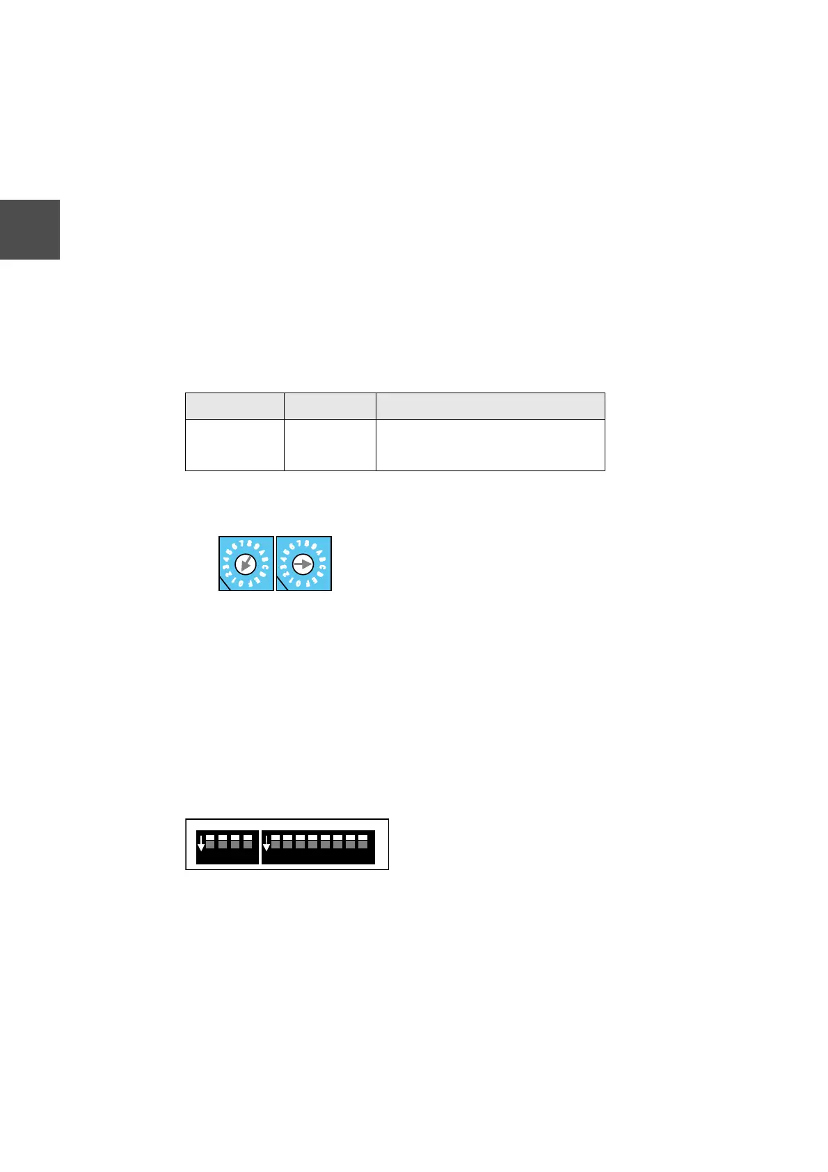
Flipping the lever of a DIP switch bit up sets it to ON,
and flipping it down sets it to OFF.
ON
1 2 3 4
ON
1 2 3 4 5 6 7 8
MODE2 MODE
 Loading...