Basi
nsta
at
on and Operat
on G
de T
Ser
es D
ta
olid
tate
o
t
tarters 1
1250A
20|Page
Chapter 4 – Programming
Introduction
It is best to operate the motor at its full load starting conditions to achieve the proper time, torque and ramp
settings. Initial factory settings are set to accommodate general motor applications and provide basic motor
protection. Advanced features must be enabled via programming. The only parameter that MUST be set by
the user is motor FLA (F001).
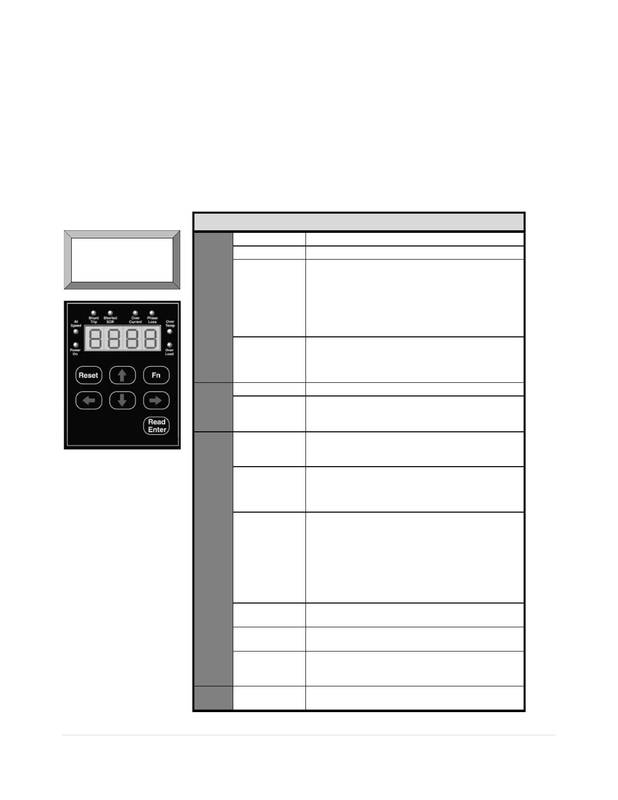
Digital Interface: The TE Series Soft Starter includes a digital keypad with eight LEDs, seven
command keys, and an LED display with four alphanumeric digits.
Figure 6.
Table 5.: TE Series Display Features
Keys
Reset Clears the Trip indication and releases the Trip Relay.
Fn Enters or exits the Program Mode.
Up and Down
Arrows
Navigates through the Status Display Mode, scrolls up
and down through the Function List, increases or
decreases the value of the active (flashing) digit and
scrolls through the fault history. When entering values,
holding the key down for more than 2 seconds will
activate Auto-step, which increases its rate the longer the
key is held down.
Right and Left
Arrows
Each key press shifts the active (flashing) digit to the right
or left by one position, allowing you to change higher
values of functions without waiting to Auto-step though
large numbers.
Green
LEDs
Power On Control power is available at A1 and A2
At-
Speed
The motor is at full power and the Bypass Contactor has
been commanded to pull in.
The SCRs are at full conduction and current has dropped.
Yellow
LEDs
Shunt
Trip
Power is flowing to the motor in the Off mode. See section
5.6.8.a of the Advanced Installation, Operation and
Programming Manual for additional information.
Shorted
SCR
There is no voltage drop across at least one SCR phase
assembly, indicating that at least one SCR is shorted.
See section 7 of the Advanced Installation, Operation and
Programming Manual for additional information.
Over
Current
Overcurrent LED lights for three sets of fault conditions:
1) During start, the unit saw current exceed the normal
rate of increase in the first 250ms.
2) During Run, current exceeded either the OC setting in
F042 for the delay set in F043. This LED will be
accompanied by oCA, oCC or oCd on the display.
3) The unit has seen a Short Circuit exceeding 10x FLA
for 12.5ms. This LED will be accompanied by SCA,
SCC or SCD display.
Phase
Loss
One or more of the phase currents dropped below the
threshold during starting or running.
Over
Temp
Starter has tripped due to excess heat sink temperature.
This will automatically reset.
Over
Load
Starter has tripped due to the Thermal Register reaching
0000. The Overload must reset before this fault can be
cleared.
Display 8888.
4 digit 7 segment display with a decimal point on the right
side indicating Phase A.
MOTOR FLA (F001)
must be programmed
for unit to operate!
Buy: www.ValinOnline.com | Phone 844-385-3099 | Email: CustomerService@valin.com

 Loading...


