-8‑
2.1. PROFIBUS connector
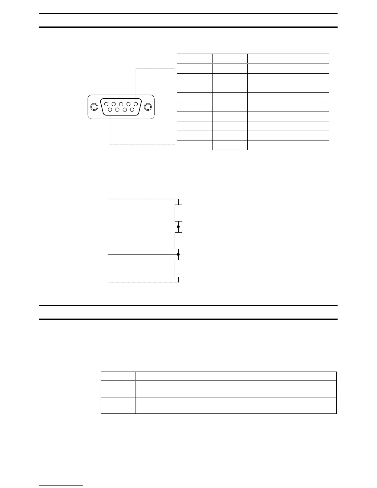
Used to connect PROFIBUS network cables. The connector is a D-Sub connector with 9 pin
female and the connector pin allocation described below follows the PROFIBUS standard.
The PDP002Z has no termination resistor. Therefore, termination resistors need to be
connected to the station on each side of the PROFIBUS network or the master, as shown in
the figure below. (The PROFIBUS connector with termination resistor are recommended.)
2.2. Status indicator
The PDP002Z has two LEDs, ST (status) and DX (data exchange) to indicate the
statuses of PROFIBUS-DP and the PDP002Z itself.
ST (Status): Red LED
LED Meanings
Off No diagnostics present
Flashes Waiting for parameterisation or configuration
Lights
DP status error
* For example, a station address is not set correctly.
DX (Data exchange): Green LED.
Indicates the status of the PROFIBUS network.
It lights when the PDP002Z is on-line and data exchange is possible.
Pin number Symbol Signal type
1 NC Reserved
2 NC Reserved
3 RxD/TxD-P Send/receive data (+)
4 CNTR-P Control signal
5 DGND 0V (Insulated from the inside)
6 VP +5V power
7 NC Reserved
8 RxD/TxD-N Send/receive data (-)
9 NC Reserved
390 ohm
*
220 ohm
*
RxD/TxD-P(3 pin)
390 ohm
*
RxD/TxD-N(8 pin)
DGND(5 pin)
* 1/4W or more is recommended.
15 4 3 2
9 8 7 6

 Loading...


