39
Technical Information
Service Manual
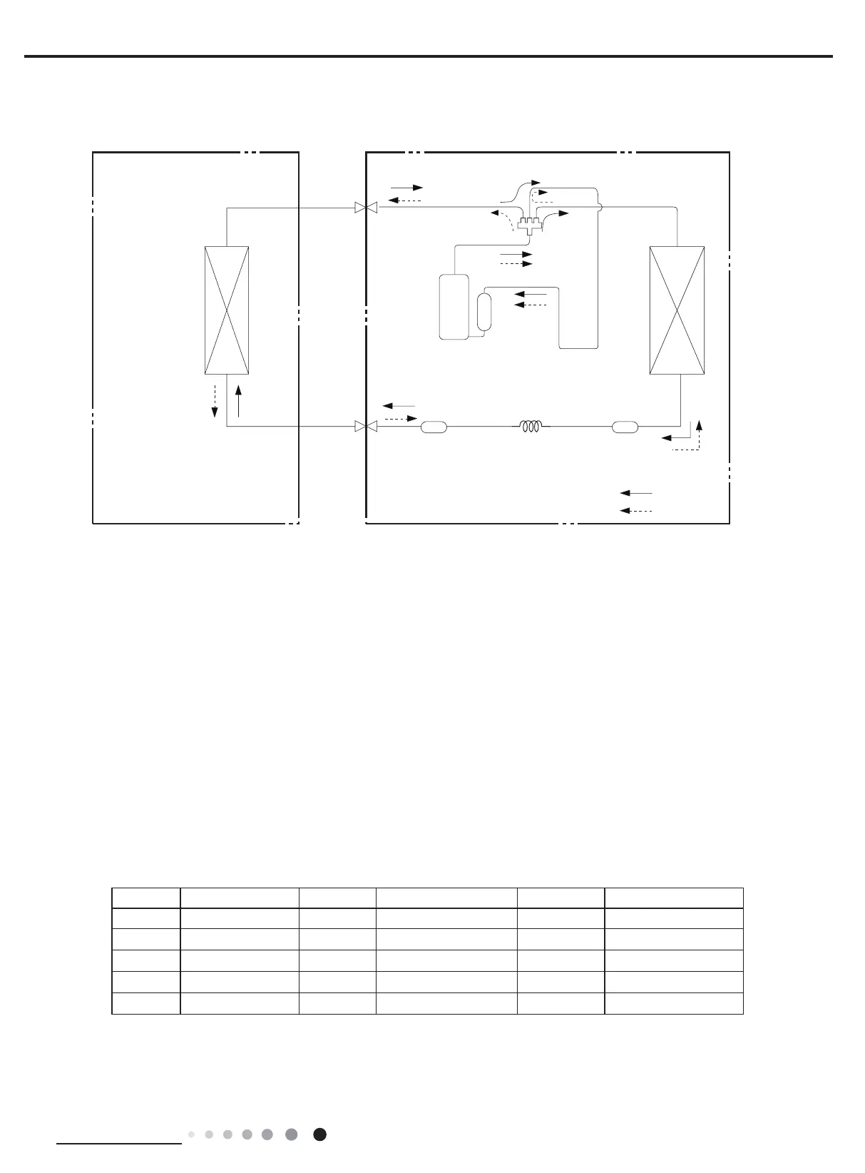
COOLING
HEATING
4-Way valve
Discharge
Suction
Heat
exchanger
(evaporator)
Heat
exchanger
(condenser)
Valve
Valve
Liquid pipe
side
Gas pipe
side
Strainer
Strainer
Capillary
Accumlator
Compressor
Connection pipe specication:
Liquid pipe:1/4"
Gas pipe:3/8"(TW09HQ1C8D TW09HQ1B8A TW09CQ2B8D TW09HQ2C2D TW12HQ1C8D TW12HQ1B8A )
Gas pipe:1/2"(TW12HQ2C2D TW12CQ2B8D TW18HQ1C8D)
Gas pipe:5/8"(TW18HQ2C2D TW24HQ1C8D TW24HQ2C2D)
4. Refrigerant System Diagram
5. Electrical Part
5.1 Wiring Diagram
● Instruction
Symbol Symbol Color Symbol Symbol Color Symbol Name
WH White GN Green CAP Jumper cap
YE Yellow BN Brown COMP Compressor
RD Red BU Blue Grounding wire
YEGN Yellow/Green BK Black / /
VT Violet OG Orange / /
Note: Jumper cap is used to determine fan speed and the swing angle of horizontal lover for this model.
 Loading...