49
Installation and Maintenance
Service Manual
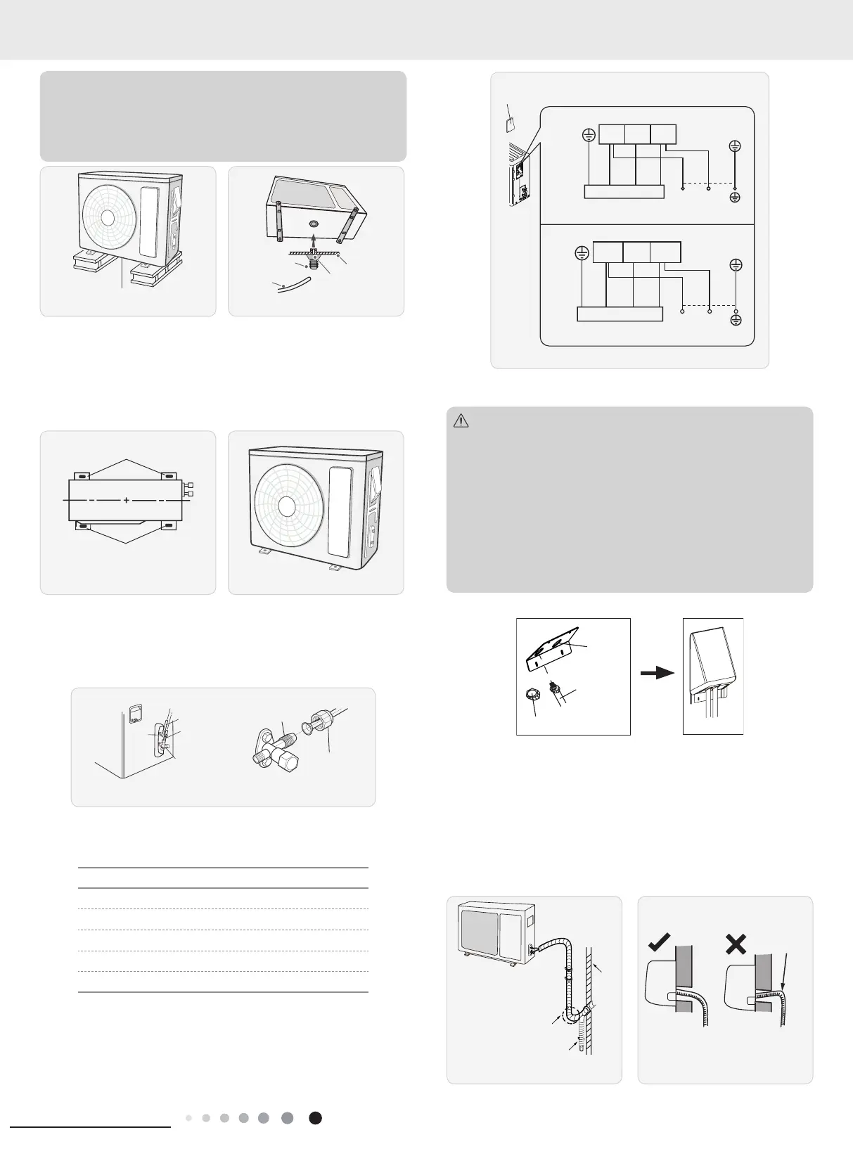
(4) For the unit with cooling capacity of 2300W~5000W, 6
expansion screws are needed; for the unit with cooling capacity
of 6000W~8000W, 8 expansion screws are needed; for the
unit with cooling capacity of 10000W~16000W, 10 expansion
screws are needed.
Chassis
Outdoor drain join
e
Drain vent
Fig.18
Fig.19
At least 3cm above the floor
2. Install Drain Joint(Only for cooling and heating unit)
(1) Connect the outdoor drain joint into the hole on the chassis.
(2) Connect the drain hose into the drain vent.(As show in Fig.19)
3. Fix Outdoor Unit
(1) Place the outdoor unit on the support.
(2) Fix the foot holes of outdoor unit with bolts.(As show in Fig.20)
Fig.20 Fig.21
4. Connect Indoor and Outdoor Pipes
(1) Remove the screw on the right handle of outdoor unit and
then remove the handle. (As show in Fig.21)
(2) Remove the screw cap of valve and aim the pipe joint at the
bellmouth of pipe. (As show in Fig.22)
gas pipe
Liquid pipe
Liquid
valve
gas valve
Pipe joint
Fig.22
(3) Pretightening the union nut with hand.
(4) Tighten the union nut with torque wrench .
Refer to the following table for wrench moment of force
:
Piping size (inch) Tightening torque (N
.
m)
1/4 15~20
3/8 30~40
1/2 45~55
5/8 60~65
3/4 70~75
5. Connect Outdoor Electric Wire
(1) Remove the wire clip; connect the power connection wire and
signal control wire (only for cooling and heating unit) to the wiring
terminal according to the color; x them with screws. (As show in
Fig.23)
Fig.23
cable cross
plate sub-assy
L1(1)
09K(208/230V~) / 12K(208/230V~) / 18K / 24K:
09K(115V~) / 12K(115V~):
POWER
2
black
L2(3)
(brown)
black
(brown)
black
green
Indoor unit connection
(yellow-
L1 L2
green)
green
(yellow-
green)
green
(yellow-
green)
green
(yellow-
green)
white
(blue)
white
(blue)
white
(blue)
white
(blue)
red
red
(brown)
(brown)
N(1)
POWER
2
N
Indoor unit connection
L(3)
L
black
Note: the wiring connect is for reference only,please refer to the
actual one.
(1) After tightening the screw, pull the power cord slightly to
check if it is rm.
(2) Never cut the power connection wire to prolong or shorten
the distance.
(3) The connecting wire and connection pipe cannnot touch
each other.
(4) Top cover of outdoor unit and electric box assembly should
be xec by the screw. Otherwise, it can cause a re, or short
circuit caused by water or dust.
Note:
Install the over line pipe
wire pipe
wire-passing
hole
Fixed nut
Finish
6. Neaten the Pipes
(1) The pipes should be placed along the wall, bent reasonably
and hidden possibly. Min. semidiameter of bending the pipe is
10cm.
(2) If the outdoor unit is higher than the wall hole, you must set
a U-shaped curve in the pipe before pipe goes into the room,
in order to prevent rain from getting into the room. (As show in
Fig.24)
can't raise
upwards.
Fig.24 Fig.25
U-shaped curve
8. Installation
 Loading...