1. Pull the battery tab out from daughter card enclosure.
NOTE: Red LED light will blink to indicate that procedure is functioning.
2. Remove the controller cover and guide the IoT wire harness
(black & white) out through the notch on the bottom of the controller
case.
3. Reattach the controller cover. Be careful to keep the IoT wire harness
and the connection cables in the notch. Do not pinch. Do not kink.
4. Route the IoT wire harness under the controller case and then
between the case and valve body as shown. Let the end of the
harness rest on the top of the controller case.
5. Line up the velcro strips on the daughter card enclosure to the
corresponding strips on the controller case (Location "A")
and attach. If there is any obstacle to mounting at location "A",
use location "B".
6. Connect the daughter card wire harness connection. Listen for
the "click" indicating a secure connection.
7. Coil the daughter card connection harness neatly and make
sure the harness and connectors are above the controller case.
8. Test Run.
9. Commit the daughter card according to GP's Instructions.
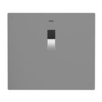
Valve Body Assembly
*Parts may vary in appearance depending on model#, TET2LBi2#SS shown.
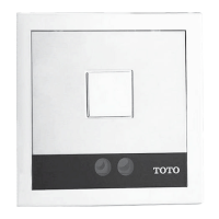
Cover Plate Manual (0GU3094)Frame
ECOPOWER Concealed Flush Valve
Daughter Card Installation Manual
0GU3097 Rev.A
LED Light
Battery Tab
NOTE: Install the ush valve rst. Follow the instructions in the Flush Valve Installation & Owners Manual 0GU3094.
TET2UBi2#SS/TET2LBi2#SS/TET2GBi2#SS/TET3UBi2#SS/TET3LBi2#SS/TET3GBi2#SS
Daughter Card Enclosure
Follow the instructions in the Flush Valve Installation Instruction Manual
(0GU3094) to complete the installation.
Please contact TOTO at 888-295-8134, or Georgia Pacic at 800-890-0896 or
KOLOhelp@gapac.com for any questions regarding installation or maintenance.
GP Part # 61000KB
TOTO Part # THP3395
NOTE:
“CLICK” sound.
Manual
(Refers to this document)
KEEP THIS DOCUMENT FOR REFERENCE AND MAKE AVAILABLE FOR MAINTENANCE PERSONNEL.
Please read and adhere to these notes. Failure to do so could result in personal injury, risk of re or smoke and/or property damage.
- Install the product according to installation instructions.
- Install the product in the correct vertical orientation.
- Do not use or operate the product with it’s covers removed.
Velcro
TOP
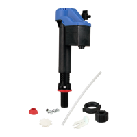
INCLUDED PARTS
WARNINGS
INSTALLATION PROCEDURE
Make sure there is enough space for the daughter card enclosure to attach at
location "A" or "B" without interference. A minimum of 13/16” (20mm) clearance
around the controller case is required.
Do not drop enclosure! Handle with care!
BEFORE INSTALLATION
Connection cables
Location “A”
Velcro
Location “B”
Velcro
13/16”
(20mm)
13/16”
(20mm)
Space
requirement
Location “A”
Location “B”
Space
requirement