5 of 12
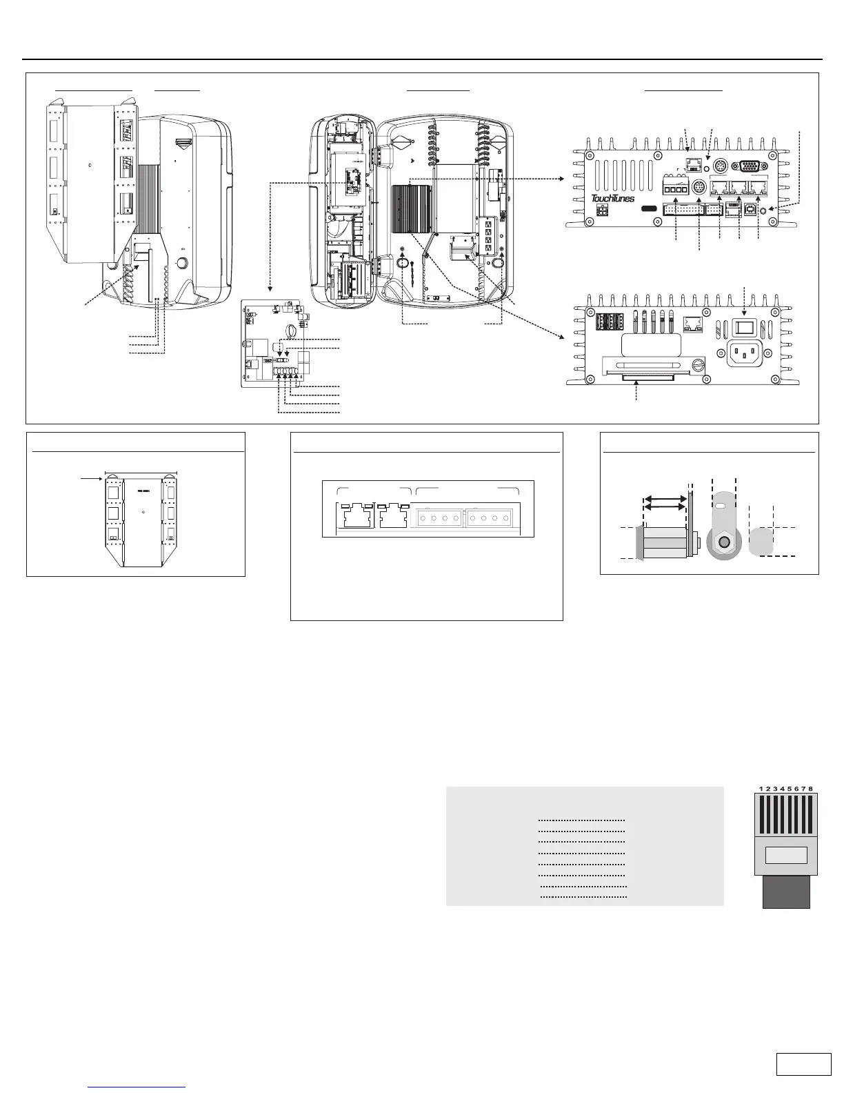
Ovation components
Rear panel
• Cable channels: All cables are routed through the cable channels on
the rear of the unit.
• Volume buttons: Provide manual control of the jukebox volume.
• Night Mode button: Turns off the monitor, lights, and bill collector.
The computer remains active so it can call the TouchTunes server.
Inside Ovation
• Wire strain-relief bracket: This is where cables are routed out of the
jukebox and into the cable channels. Once the bracket is tightened,
the cables are secure so they cannot be pulled out.
• Wall bracket screws: Used to secure the jukebox to the wall bracket.
Connector panels
• Phone line connector: Connects the jukebox to a phone line so it can
communicate with the TouchTunes server.
• Reset button: Press to restart the jukebox.
• Manager button: Activates the operator menu which enables you to
configure all Ovation settings.
• Microphone: For connection of a balanced, low-impedance (less than
600 ohms), dry contact microphone. Use the supplied four-position
Euroblock connector to attach the microphone cable.
• Auxiliary sound input: Use the supplied RCA-to-DIN adapters to
attach an auxiliary sound source input.
• Audio outs: Audio out 1 and 2 are connected to the integrated
jukebox amplifier by default. If required audio out 1, 2 and 3 can be
connected to external sound systems via standard category 5 cable.
You can purchase prewired cable, or wire your own cable as follows:
If you need RCA outputs, a category 5 to RCA converter (Bal/Umbal
DI box) is available from TouchTunes (part number 700003-001).
• Amplifier: Provides amplification for external speakers in two zones.
• System power switch: Turns off all power to the jukebox.
• Hard drive slot: The hard drive that holds all songs is installed here.
Mount top of bracket
65 inches from floor
25.1 inches
NETWORK
2
USB
13
ON OFF
Serial No.
ACT
LNK
100 - 120VAC
50/60Hz 2.0A MAX.
NO USER-SERVICEABLE PARTS INSIDE
Bottom
System power switch
VIDEOKBDTELCO
AUDIO OUT
13
LINE IN
RST
USBDMX
MNG
COM1
MIC
12
P
W
R
D
I
A
G
HD
TO CTL
P/N: 300114-
2
SW
(-) (+)
Top
Connector Panels
Hard drive
Phone line connector
Mounting Height
Amplifier Connectors
5/8"
16 mm
Audio out connectors
Wire strain-
relief bracket
Volume increase
Volume decrease
Night mode button
Cable
channel
(Note: Buttons are slightly recessed.)
Wall bracket screws
Inside OvationRear PanelMounting Bracket
Lock
BZONEA BZONEA
-L+-R+ -L+-R+
Zone B is connected to Audio Out 2.
Zone A is connected to Audio Out 1.
Euroblock connectors provide audio out at
150W/4 Ohms per channel. Must be used with
full-range speakers.
Audio inputs
Speaker connectors
Connector lights
Green: Power.
Yellow: Sound presence, blink with
sound from mid-level and up.
Power/Standby lights (not shown)
Green: Amp is operating normally.
Red: Amp is in standby mode or an
abnormal condition has been
encountered (overheat, output short)
Reset button
Microphone connector
Auxilliary sound input
Manager button
Top
Manager button
Volume up
Volume down
Night mode button
Standby light
Power on light
Control Board
1
2
3
4
5
6
7
8
white + orange
orange
white + green
blue
white + blue
green
white + brown
brown
white + orange
orange
white + green
blue
white + blue
green
white + brown
brown
1
2
3
4
5
6
7
8
Near
End
Color Color
Far
End
Straight-through catagory 5 cable wiring
RJ45 connector