ISC - Functions
of Engine EC
U
2
. ROTARY SOLENOID TYPE ISC VALV
E
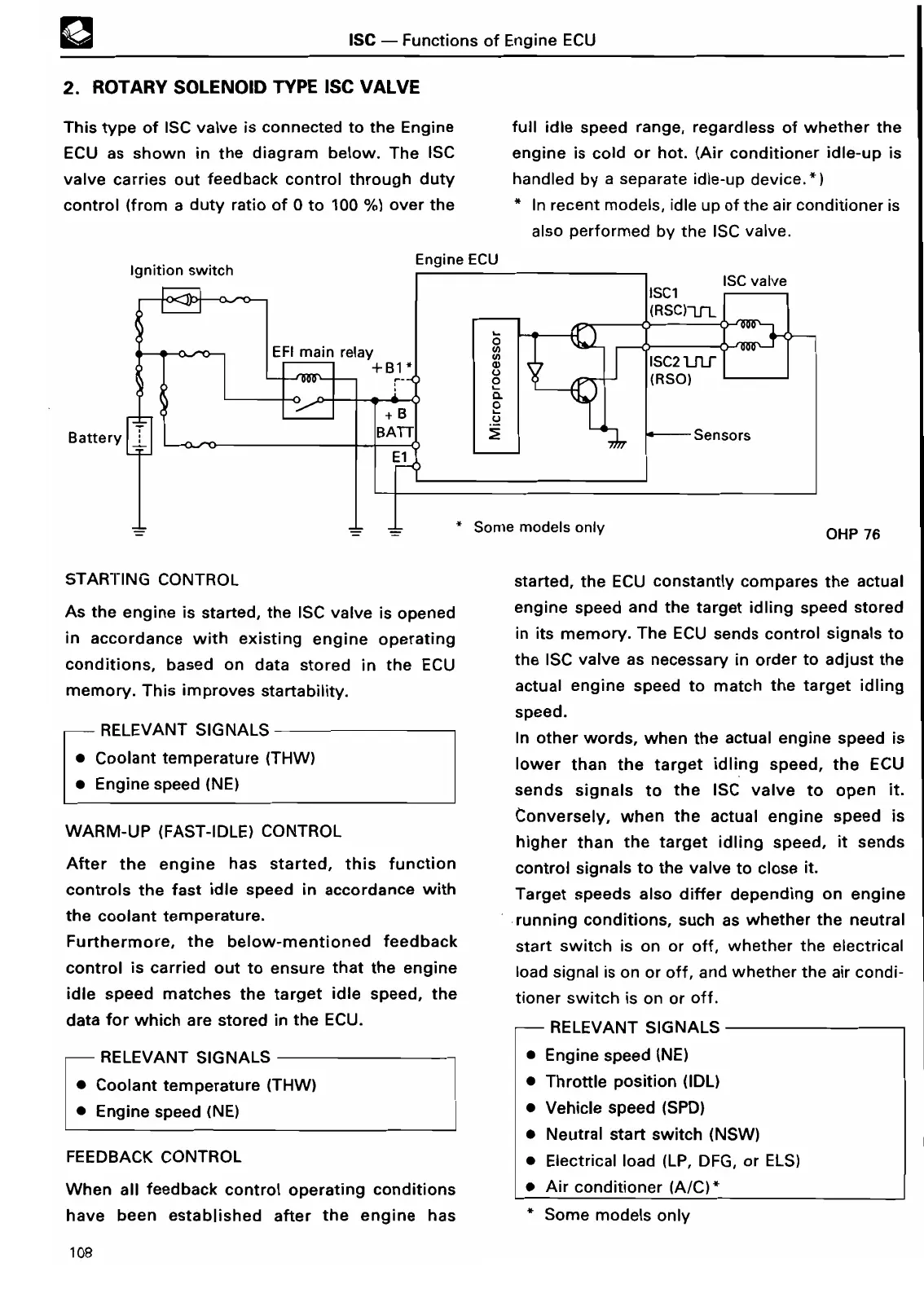
This type of ISC valve is connected to the Engine
ECU as shown in the diagram below
. The ISC
valve carries out feedback control through duty
control
(
from a duty ratio of 0 to
100 %)
over th
e
Battery
full idle speed range, regardless of whether the
engine is cold or hot
. (Air conditioner idle-up is
handled by a separate idle-up device
.*
)
In recent models, idle up of the air conditioner is
also performed by the ISC valve
.
OHP 7
6
STARTING CONTRO
L
As the engine is sta
rt
ed,
the ISC valve
is opened
in accordance with existing engine operating
conditions, based on data
stored in the ECU
memory
. This improves startability
.
- RELEVANT SIGNAL
S
• Coolant temperature (THW)
• Engine speed (NE
)
WARM-UP (FAST-IDLE) CONTRO
L
After the engine has started, this function
controls the fast idle speed in accordance with
the coolant temperature
.
Fu
rt
hermore, the below-mentioned feedback
control is carried out to ensure that the engine
idle speed matches the target idle speed, the
data for which are stored
in the ECU
.
F
RELEVANT SIGNALS
Coolant temperature (THW)
Engine speed (NE
)
FEEDBACK
CONTRO
L
When all feedback control operating conditions
have been established after the engine has
started, the ECU constantly
compares the actual
engine speed and the target idling speed stored
in its memory
. The ECU sends
control signals to
the ISC valve
as necessa
ry in order to
adjust the
actual engine speed
to match the
target idling
speed
.
In other words, when the actual engine speed is
lower than the target idling speed, the ECU
sends signals to the
ISC valve to
open it
.
Conversely,
when the actual engine speed is
higher than the target idling speed, it sends
control signals to the valve to close it
.
Target speeds also differ depending on engine
running conditions, such as whether the neutral
start switch is on or off, whether the electrical
load signal is
on or off, and whether the air condi-
tioner switch is on or off
.
RELEVANT SIGNALS
• Engine speed (NE
)
• Throttle position (IDL)
• Vehicle speed (SPD
)
• Neutral sta
rt
switch (NSW
)
• Electrical
load (LP, DFG, or ELS)
• Air conditioner (A/C)
*
* Some models onl
y
108