®
OUTLINE OF
TCCS - System Descriptio
n
2
. CONSTRUCTION OF ENGINE CONTROL SYSTE
M
BLOCK DIAGRA
M
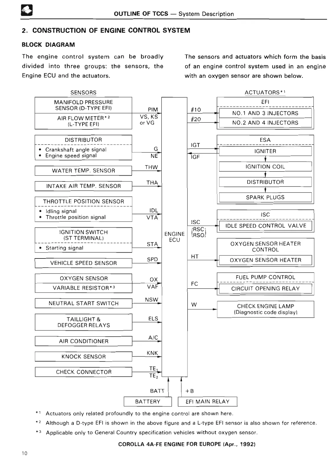
The engine control system can be broadly The sensors and actuators which form the basis
divided into three groups
: the sensors, the of an engine control system used in an engine
Engine ECU and the actuators
. with an oxygen sensor are shown below
.
SENSOR
S
MANIFOLD PRESSURE I I I I EF
I
SENSOR
(D-TYPE EFI
)
AIR FLOW METER*2
(L-TYPE EFI
)
DISTRIBUTOR
----------------------------
• Crankshaft angle signa
l
• Engine speed signa
l
WATER TEMP
. SENSO
R
INTAKE AIR TEMP
. SENSO
R
THROTTLE
POSITION SENSO
R
• Idling signa
l
• Throttle position signa
l
IGNITION SWITCH
(ST TERMINAL
)
• Starting signa
l
VEHICLE SPEED SENSO
R
OXYGEN SENSO
R
VARIABLE
RESISTOR-
3
NEUTRAL START SWITC
H
TAILLIGHT
&
DEFOGGER RELAY
S
AIR CONDITIONE
R
KNOCK
SENSO
R
CHECK CONNECTOR
OXYGEN SENSOR HEATER
CONTRO
L
OXYGEN SENSOR HEATE
R
FUEL PUMP CONTRO
L
CIRCUIT OPENING RELA
Y
CHECK ENGINE LAMP
(Diagnostic code display
)
PIM ~10
VS, KS
#20
or VG
G
N
E
TH
W
TH
A
ID L
T
A
ST
A
SP
D
OX
VA
F
NS
W
EL
S
A/
C
KN
K
T
E
TE
IG
T
IG
F
IS
C
RSC
ENGINE IRSO
I
ECU
H T
F
C
W
BATT I 1
+1
3
BATTERY I I EFI MAIN RELA
Y
*
1
*
2
*3
Actuators only related profoundly to the engine control are shown here
.
Although a D-type EFI is shown in the above figure and a L-type EFI sensor is also shown for reference
.
Applicable only to General Country specification vehicles without oxygen sensor
.
ACTUATORS*
'
NO
.1 AND 3 INJECTOR
S
NO
.2 AND 4 INJECTOR
S
ES
A
IGNITE
R
i
IGNITION COI
L
i
DISTRIBUTO
R
t
SPARK PLUG
S
IS
C
IDLE SPEED
CONTROL VALV
E
COROLLA
4A-FE ENGINE FOR EUROPE
(
Apr
., 1992)
10