ELECTRONIC CONTROL SYSTEM
- G and NE Signal Generator
s
7 G signal (1 pickup coil, 1 tooth)
NE signal
(2 pickup coils, 4 teeth
)
Engine ECU
2
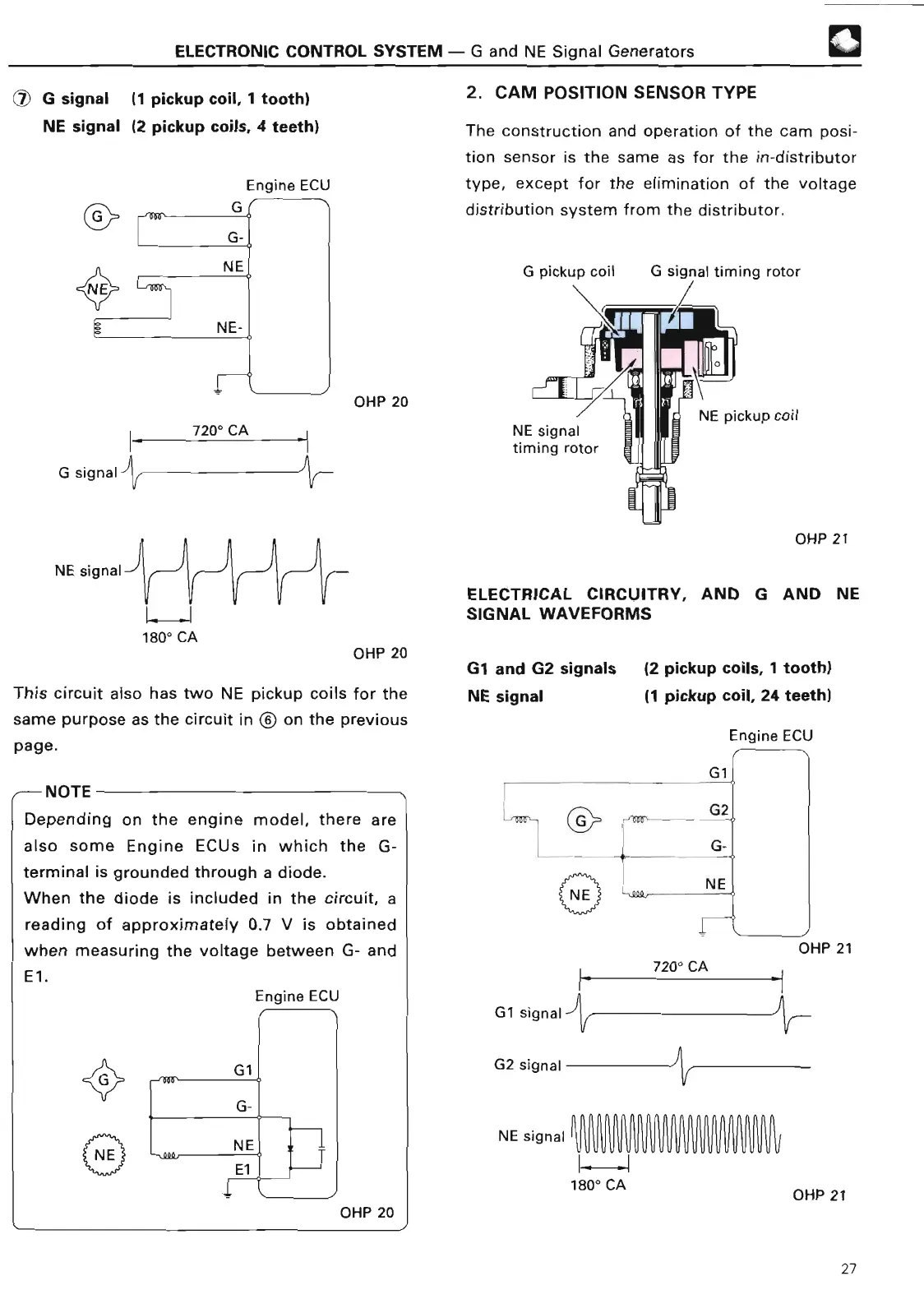
. CAM POSITION SENSOR TYP
E
The construction and operation of the cam posi-
tion sensor is the same as for the in-distributor
type, except for the elimination of the voltage
distribution system from the distributor
.
G pickup coil
G signal
timing roto
r
NE
signal--'
7200
C
A
~
.
y
i
1800
CA
j
OHP 2
0
OHP 2
0
This circuit also has two NE pickup coils for the
same purpose
as the circuit in © on the previous
page
.
~--
NOT
E
Depending on the engine model, there are
also some Engine ECUs
in which the G-
terminal is grounded through a diode
.
When the diode is included in the circuit, a
reading of approximately
0
.7 V is
obtained
when measuring the voltage between G- an
d
El
.
Engine ECU
OHP 20
NE signal
timing rotor
NE pickup coil
OHP 2
1
ELECTRICAL CIRCUITRY,
AND G AND NE
SIGNAL WAVEFORM
S
G1 and G2
signals
(2 pickup coils, 1 tooth)
NE signal
(1 pickup coil, 24 teeth
)
Engine EC
U
Gl
f
L
ml-
G1 signa
l
G2 signal -
NE signal
11--
.
1
1800
CA
G
2
NE
I
OHP 2
1
720° CA
V
OHP 21
27