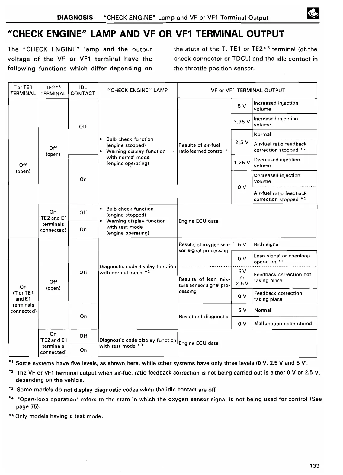
DIAGNOSIS
- "CHECK
ENGINE" Lamp and VF or VF1 Terminal Outpu
t
"CHECK ENGINE"
LAMP AND VF OR VF1 TERMINAL OUTPU
T
The "CHECK ENGINE"
►
amp and the output
voltage of
the VF or VF1
terminal have the
following functions which differ depending on
the state
of the T, TE1 or TE2*5
terminal
(of-the
check connector
or TDCL)
and the idle contact in
the throttle position sensor
.
TorTE1
TE2+5
IDL
"
CHECK
ENGINE" LAMP
VF or VF1 TERMINAL OUTPU
T
TERMINAL TERMINAL
CONTACT
5 V
Increased injectio
n
volum
e
3
.75 V
Increased injectio
n
Off
volum
e
Norma
l
• Bulb check function
5
V
2
---------------------- --------
-
(en ne
stopped
)
9i
Results of air-fuel
.
Air-fuel ratio feedbac
k
Off
• Warning display function
ratio learned control
1
correction stopped *
z
(open)
with normal mode
sed injectio
n
Off
(engine operating)
1
.25 V
Dolum
e
(open)
Decreased injectio
n
On
volum
e
0 V
--- ------ - - --- -- - -------
-
Air-fuel ratio feedbac
k
correction stopped +
2
On
Off
• Bulb check functio
n
(
TE2 and
El
(
engine stopped
)
di
l
f
i
i
•
W
i
ECU
d
E
sp
unct
o
n
arn
ng
ay
ng
ne
at
a
terminals
O
test mod
e
wit
h
connected)
n
(
engine operating)
Results of oxygen sen-
5 V
Rich signa
l
i l i
sor s gna
process
ng
0 V
Lean signal or openloo
p
operation *
4
Diagnostic code display function
----------------------------
-------
---
----------------------------------
-
Off
with normal mode *'
5V
Feedback correction no
t
Off
Results of lean mix-
o
r
5
V
2
taking plac
e
On
ture sensor signal pro-
.
(open
)
IT or TE1
cessing
0 V
Feedback correctio
n
and E1
taking plac
e
terminal
s
connected)
5 V
Norma
l
l
f di
i
On
Resu
ts o
agnost
c
0 V
Malfunction code store
d
On
Of
f
(TE2 and E1
Diagnostic code
display
function
ECU
d
E
i
at
a
ng
n
e
terminal
s
connected)
On
with test mod
e
*t Some systems have five levels, as shown here, while other systems have only three levels (0 V, 2
.5 V and 5
V)
.
`2 The VF or VF1 terminal output when air-fuel ratio feedback correction is not being carried out is either 0 V or 2
.5 V,
depending on the vehicle
.
*3 Some models do not display diagnostic codes when the idle contact are off
.
*4 "Open-loop operation" refers to the state in which the oxygen sensor signal is not being used for control (See
page 75)
.
50n1y models having a test mode
.
133