ELECTRONIC CONTROL SYSTEM
- G and NE Signal Generator
s
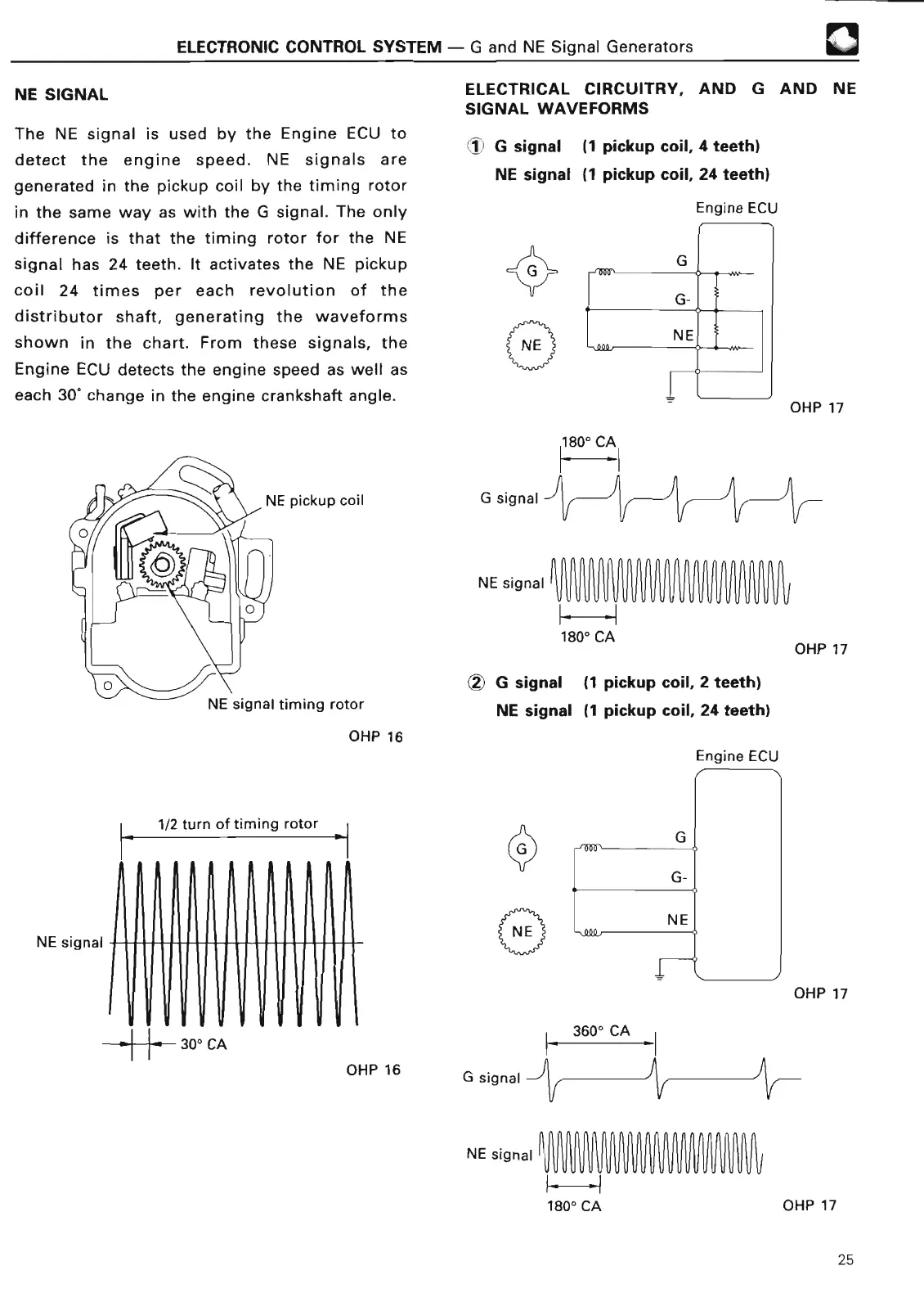
NE SIGNA
L
The NE signal is used by the Engine ECU to
detect the engine speed
. NE signals are
generated in the pickup coil by the timing rotor
in the same way as with the G signal
. The only
difference is that the timing rotor for the NE
signal has 24 teeth
. It activates the NE pickup
coil 24 times per each revolution of the
distributor shaft, generating the waveforms
shown in the chart
. From these signals, the
Engine ECU detects the engine speed as well as
each 30° change in the engine crankshaft angle
.
NE signal
timing roto
r
OHP 1
6
NE signal
1/2 turn of timing rotor
ELECTRICAL
CIRCUITRY, AND G AND NE
SIGNAL WAVEFORM
S
1 G signal
(1 pickup coil, 4 teeth)
NE signal
(
1 pickup coil,
24 teeth
)
Engine EC
U
NE signal
OHP 17
1800
CA
OHP 1
7
(2) G signal (
1 pickup coil, 2 teeth)
NE signal
(
1 pickup coil, 24 teeth
)
Engine ECU
OHP 1
7
U U
rrur
1
r
30° CA
rrr
OHP 16
G signa
l
NE signal
180° CA
OHP 17
25