EFI - Fuel Syste
m
CURRENT CONTROL METHOD (for 4A-GE
engine
with D-type EFI
)
In injectors that use this method, the solenoid
resistor is eliminated, and a low-resistance
injector is connected directly to the battery
.
Current flow is controlled by switching a
transistor in the Engine ECU on and off
.
When the injector plunger is pulled in, a heavy
current flows, causing the amperage to rise
quickly
. This causes the needle valve to open
quickly, resulting in improved injection response
and reduced ineffective injection duration
.
While the plunger is held in, the current is
reduced, preventing the injector coil from
generating heat, as well as reducing power
consumption
.
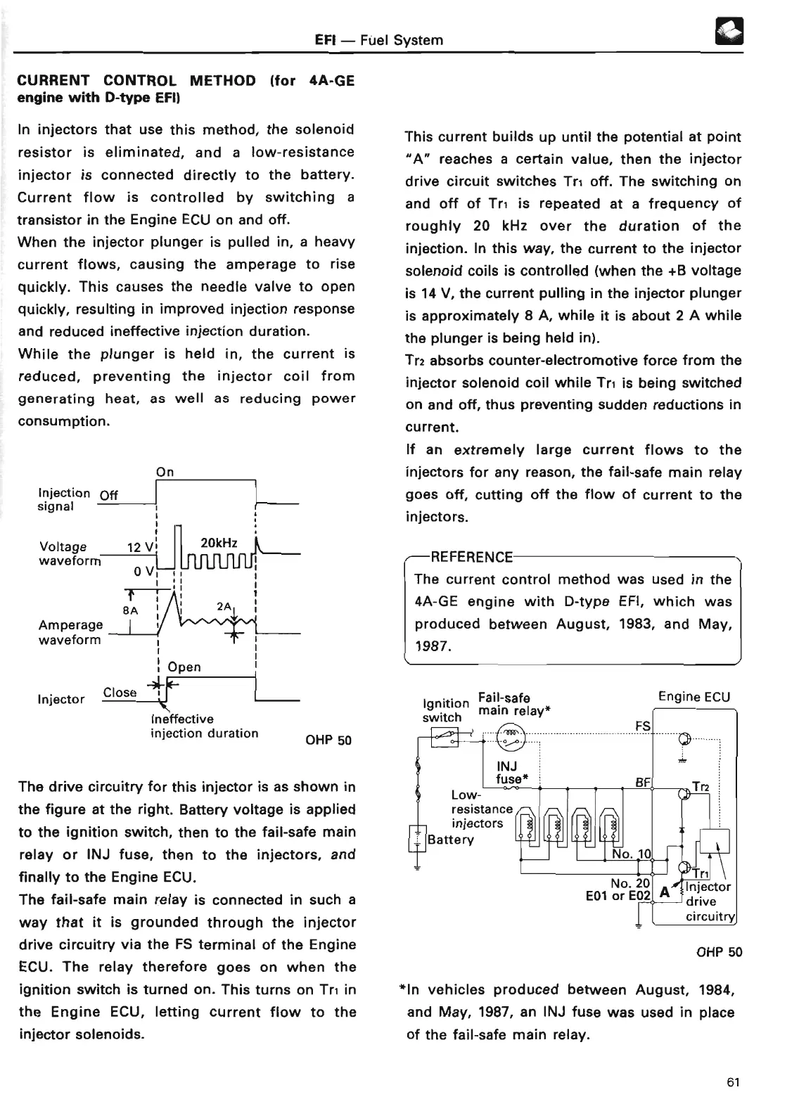
On
Injection Of
f
signal ~
Voltage 12 V, 20kHz
waveform
0V
i
~C
T
B
A
Amperage
waveform
®
This current builds up until the potential at point
"A"
reaches a certain value, then the injector
drive circuit switches Tri off
. The switching on
and off of Tr, is repeated at a frequency of
roughly 20 kHz over the duration of the
injection
. In this way, the current to the injector
solenoid coils is controlled (when the +B voltage
is 14 V, the current pulling in the injector plunger
is approximately 8 A, while it is about 2 A while
the plunger is being held in)
.
Tr2 absorbs counter-electromotive force from the
injector solenoid coil while Tri is being switched
on and off, thus preventing sudden reductions in
current
.
If an extremely large current flows to the
injectors for any reason, the fail-safe main relay
goes off, cutting off the flow of current to the
injectors
.
REFERENCE
The current control method was used in the
4A-GE engine with D-type EFI, which was
produced between August, 1983, and May,
1987
.
Ineffective
injection duration
OHP 5
0
The drive circuitry for this injector is as shown in
the figure at the right
. Battery voltage is applied
to the ignition switch, then to the fail-safe main
relay or INJ fuse, then to the injectors, and
finally to the Engine ECU
.
The fail-safe main relay is connected in such a
way that it is grounded through the injector
drive circuitry via the FS terminal of the Engine
ECU
. The relay therefore goes on when the
ignition switch is turned on . This turns on Tr, in
the Engine ECU, letting current flow to the
injector solenoids
.
Ignition
Fail-safe
switch main relay
*
Engine EC
U
OHP 5
0
*In vehicles produced between August, 1984,
and May, 1987, an INJ fuse was used in place
of the fail-safe main relay
.
61