EFI - Functions
of Engine ECU
1
3
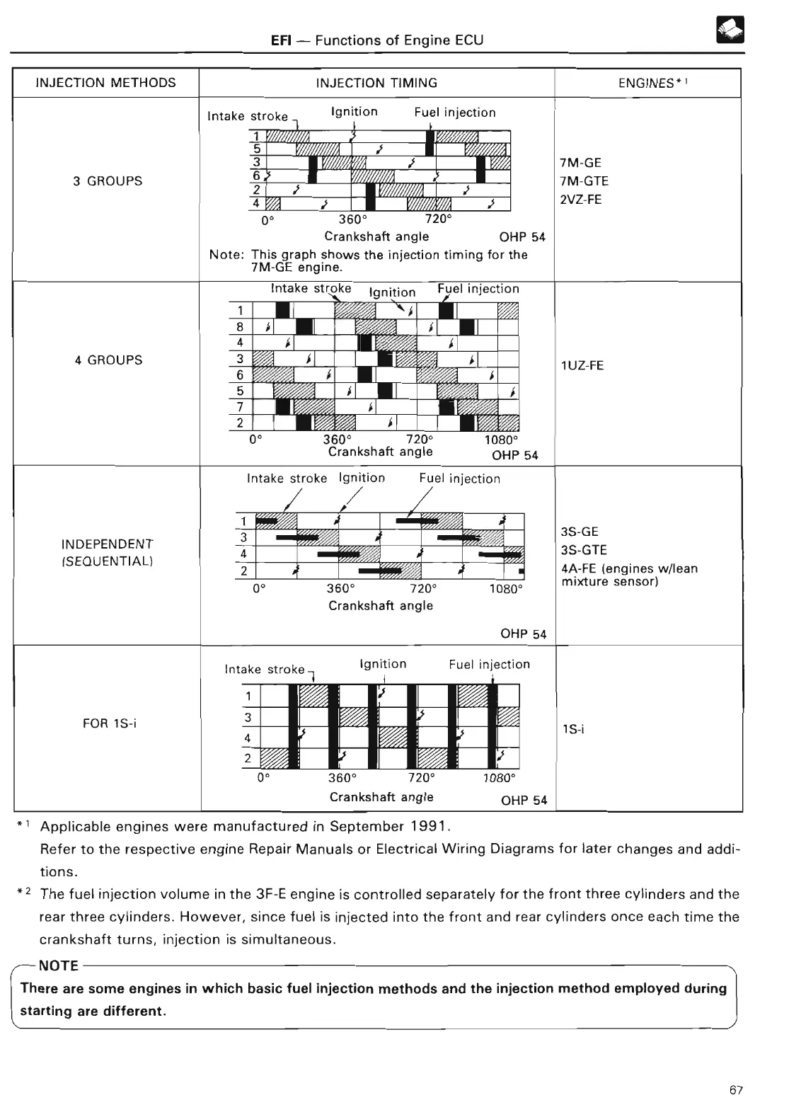
INJECTION METHODS INJECTION TIMING
ENGINES*
'
Intake stroke Ignition Fuel injectio
n
1
5
3
7M-G
E
3 GROUPS
6
7M-GT
E
4 i
s
2VZ-F
E
0°
3600 720
0
Crankshaft angle OHP 5
4
Note
: This graph shows the injection timing for th
e
7M-GE engine
.
Intake stroke Ignition Fuel injectio
n
1
f
8
i
i
1_ 01
1
4
i i
4 GROUPS
3
j
1UZ-F
E
6
i f
5
S
f
7
2
i
0
° 360° 720° 1080
°
Crankshaft angle OHP
5
4
Intake stroke Ignition Fuel injectio
n
INDEPENDENT
3S-G
E
SEQUENTIAL)
3S-GT
E
(
2
4A-FE
(
engines w/lea
n
0° 360° 720° 1080
°
Crankshaft angle
OHP 54
mixture sensor
)
FOR 1S-i
Intake stroke i Ignition Fuel injectio
n
1
t
3
4
2 t
S-
i
0` 360° 720° 1080
°
Crankshaft angle OHP 5
4
1
Applicable engines were manufactured in September 1991
.
Refer to the respective engine Repair Manuals or Electrical Wiring Diagrams for later changes and addi-
tions
.
2 The fuel injection volume in the 3F-E engine is controlled separately for the front three cylinders and the
rear three cylinders
. However, since fuel is injected into the front and rear cylinders once each time the
crankshaft turns, injection is simultaneous
.
,--
NOT
E
There are some engines in which basic fuel injection methods and the injection method employed during
starting are different
.
67